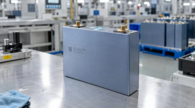
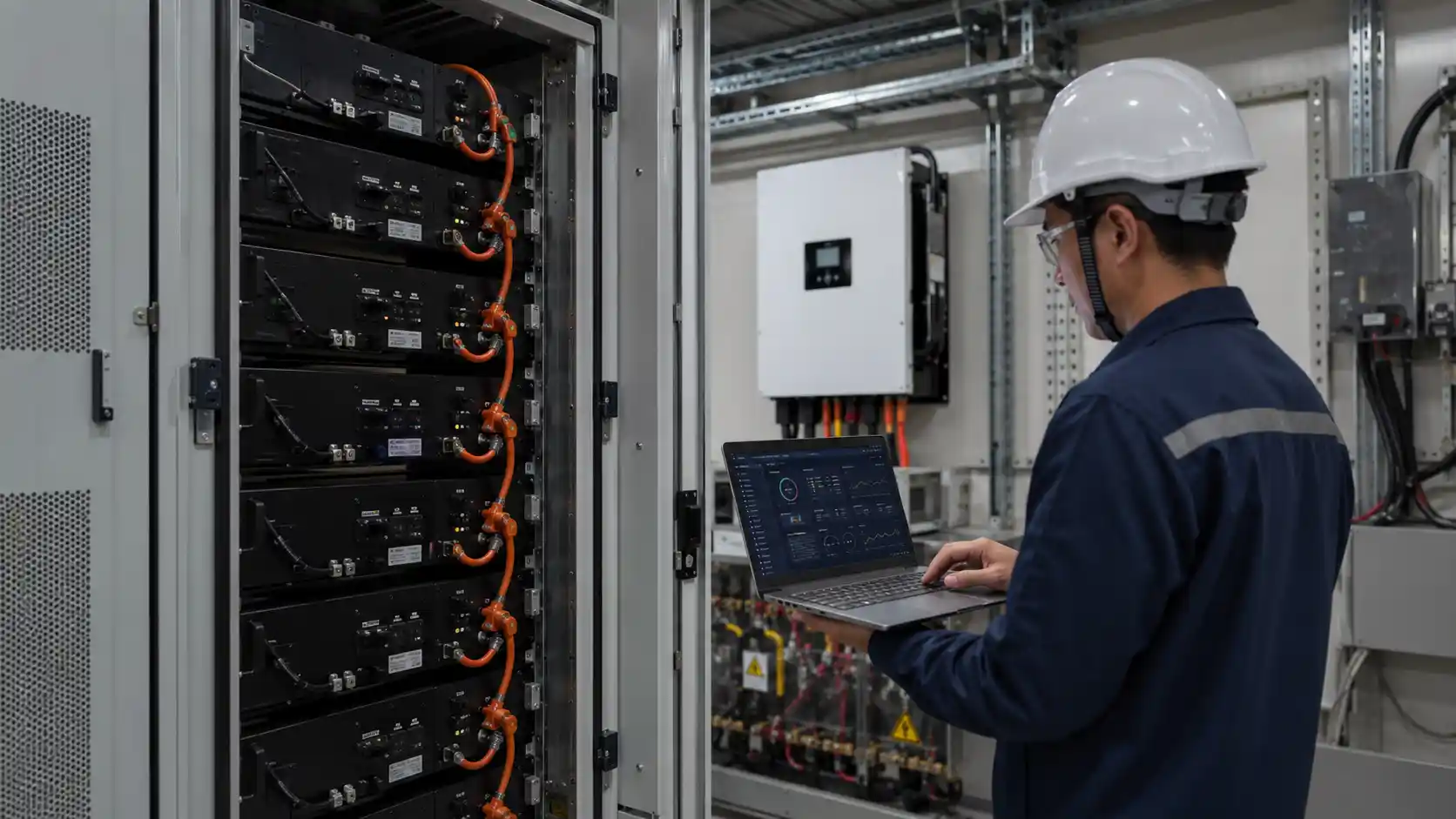
What Does BMS Stand for in a Battery?
BMS stands for Battery Management System.
In a lithium battery, the BMS is the control layer responsible for monitoring cell voltage, current, and temperature; estimating state of charge (SOC) and state of health (SOH); managing protection limits; balancing cells; recording faults; and communicating operating data to inverters, energy management systems, or other system controllers.
For stationary energy storage, however, a BMS does more than monitor the battery.
Its design can affect usable energy, charging and discharging limits, inverter communication, parallel battery operation, fault diagnostics, thermal coordination, serviceability, and long-term system reliability.
That is why BMS capability should be evaluated as part of the complete battery-system architecture rather than treated as an interchangeable circuit board.
This article focuses specifically on BMS requirements for residential, commercial, industrial, and other stationary energy storage systems rather than small consumer electronics or light-mobility batteries.
How a Battery Management System Works
A BMS continuously collects operating data from the battery and uses that information to determine whether the system can safely charge, discharge, remain online, reduce power, or shut down.
The exact architecture varies by battery voltage, pack size, application, and system topology, but most ESS battery management systems perform the following core functions.
| BMS Function | What It Does | Why It Matters in Energy Storage |
|---|---|---|
| Cell Voltage Monitoring | Measures individual cell voltages and identifies abnormal high or low voltage conditions | Helps prevent individual cells from operating outside their intended limits |
| Temperature Monitoring | Tracks cell, module, busbar, or enclosure temperatures through multiple sensors | Supports charge/discharge protection, derating, thermal management, and fault diagnosis |
| Current Measurement | Measures charging and discharging current | Supports protection logic, energy calculation, SOC estimation, and power-limit control |
| SOC Estimation | Estimates remaining usable battery capacity using current integration, voltage information, calibration, and battery models | Poor SOC estimation can result in unexpected shutdowns or underutilized capacity |
| SOH Estimation | Tracks indicators such as capacity loss, resistance growth, throughput, and operating history | Supports maintenance planning, warranty evaluation, and life-cycle management |
| Cell Balancing | Reduces differences in cell state or voltage using passive or active balancing methods | Helps prevent one cell from becoming the limiting cell in a series-connected battery |
| Protection & Fault Handling | Responds to overvoltage, undervoltage, overcurrent, short-circuit, temperature, insulation, or communication faults | Determines how safely and predictably the battery responds to abnormal operating conditions |
| Communication | Exchanges status, alarms, limits, and operating commands with inverters, PCS, EMS, displays, or service tools | Essential for closed-loop control and reliable system integration |
| Fault Logging | Records alarms, operating conditions, and historical events | Gives engineering and service teams evidence for root-cause analysis |
The original article already correctly identified monitoring, SOC/SOH estimation, balancing, protection, communication, and fault logging as central BMS functions; the main correction required is using Battery Management System as the proper BMS term and removing overly rigid performance claims.
BMS Architecture Also Matters
Not every energy storage BMS uses the same physical architecture.
A compact low-voltage battery may integrate sensing, balancing, protection, communication, and control on one primary controller.
Larger high-voltage rack or commercial systems may use a distributed architecture consisting of cell-monitoring units, module-level controllers, rack-level controls, and a master BMS that communicates with the PCS or EMS.
For buyers, this means that comparing two BMS products only by the number of supported cells or communication ports can be misleading.
The architecture should match:
- Battery voltage
- Cell and module topology
- Maximum system capacity
- Parallel or series expansion strategy
- Fault-containment requirements
- Maintenance model
- Communication architecture
- Target certification pathway
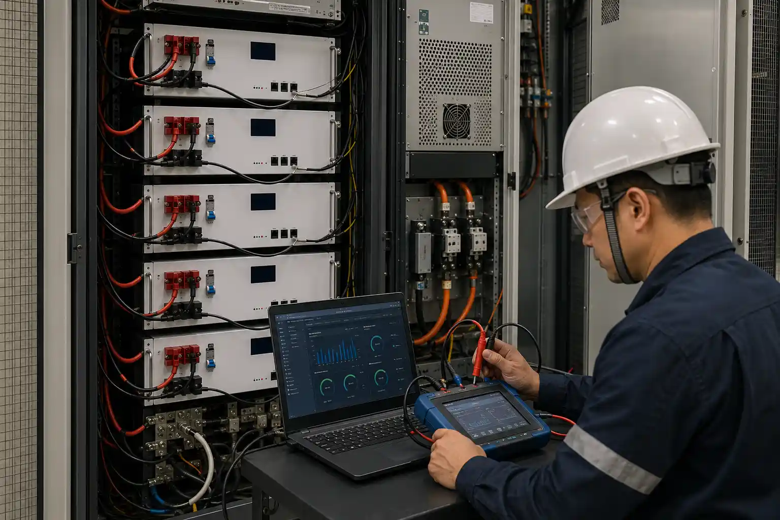
Key BMS Specifications for Energy Storage Systems
For procurement teams, the most useful BMS specification is not necessarily the largest number on a datasheet.
What matters is whether the supplier can demonstrate that the BMS performs correctly under the operating conditions of the actual battery system.
Instead of relying on generic labels such as “minimum acceptable” or “best-in-class,” buyers should ask for evidence.
| What to Verify | Evidence to Request | Buyer Evaluation Principle |
|---|---|---|
| Voltage Measurement | Accuracy specification, calibration method, test records, operating temperature conditions | Verify whether measurement performance is sufficient for the selected chemistry and protection strategy |
| Temperature Monitoring | Sensor quantity, sensor placement, calibration information, fault thresholds | Confirm the system can detect relevant thermal gradients rather than relying on one enclosure temperature |
| SOC Accuracy | Test curves across temperature, SOC range, current rate, and aging condition | Do not judge SOC performance from one headline percentage |
| SOH Method | Definition of SOH, input data, calibration method, aging validation | Ask whether SOH refers to remaining capacity, resistance, usable energy, or a composite index |
| Cell Balancing | Balancing type, current, trigger logic, operating window, historical balancing logs | Evaluate balancing against cell capacity, cell matching, charging strategy, and duty cycle |
| Protection Logic | Thresholds, delays, recovery logic, hardware protection, fault hierarchy | Confirm protection is coordinated with the battery, contactors, fuses, PCS, and system controls |
| Inverter / PCS Communication | Tested communication protocol, target equipment model, firmware version, BMS firmware version, test report | Protocol support should be validated with real hardware |
| Parallel Operation | Maximum-scale test data, addressing logic, current-sharing results, connection procedure, fault recovery | Validate at the maximum pack count planned for the project |
| Fault Logging | Event history format, timestamping, cell-level data, service export capability | Detailed logs significantly improve field diagnosis |
| Firmware Updates | Update process, firmware signing, access control, rollback, audit logs | Remote updating is useful only when change control is secure and recoverable |
| Operating Temperature | Separate charge and discharge limits, derating curves, heating strategy if available | Match limits to actual cell and pack qualification data |
| Certification Support | Certificates, test reports, models covered, hardware revision, firmware revision, configuration scope | Confirm the actual purchased configuration is included in the documented scope |
This evidence-based structure is better suited to B2B procurement than universal claims such as “8 packs minimum,” “16 packs best-in-class,” or “1–2 A balancing required,” because BMS requirements vary significantly by system design. The original specification section already covered protocol compatibility, parallel architecture, balancing, SOC, communication, firmware, certification, and temperature; those remain the right categories to evaluate.
Why BMS Quality Matters in Energy Storage Procurement
Two batteries using similar cells can perform very differently once they are integrated into real energy storage systems.
The difference often comes from system engineering rather than the cell specification alone.
A well-designed BMS can influence several commercially important areas.
Usable Energy
Battery capacity on a datasheet is not automatically equal to the energy that a customer can use.
Protection thresholds, SOC calibration, temperature limits, cell imbalance, and power derating all influence the usable operating window.
Cell Consistency Over Time
The BMS cannot turn poorly matched cells into perfectly matched cells.
However, its balancing strategy, measurement accuracy, thermal coordination, and fault detection can help prevent cell-to-cell differences from becoming an unnecessary system limitation.
Inverter and PCS Compatibility
Communication failures can make an otherwise functional battery appear unreliable.
Successful integration requires more than a statement such as “CAN supported” or “RS485 supported.”
The supplier should verify the exact communication implementation with the intended inverter or PCS, including:
- Communication interface
- Protocol version
- BMS firmware
- Inverter or PCS firmware
- Addressing method
- Charge/discharge limit handling
- Alarm behavior
- Communication recovery
- Parallel operation
Serviceability
When a battery enters protection or shuts down, the ability to reconstruct what happened can determine whether a service case takes minutes or days to diagnose.
A useful BMS should therefore preserve enough historical information to distinguish between:
- Cell voltage faults
- Temperature events
- Overcurrent events
- Communication loss
- SOC calibration issues
- Contactor faults
- External inverter or PCS conditions
Market Access
BMS design is also part of the broader battery and ESS safety architecture evaluated during certification and system qualification.
However, buyers should avoid thinking of the BMS as a standalone certification shortcut.
The relevant question is whether the complete intended battery configuration can be supported within the certification pathway required by the target market.
Common BMS Failure Modes in Energy Storage Projects
The original article identified inverter integration, parallel scaling, degradation, certification problems, and cold-climate behavior as important procurement risks. Those are useful buyer pain points and should be retained, but without unsupported financial-loss percentages.
Inverter Communication Problems
A battery may connect successfully during initial commissioning yet produce intermittent faults later because of differences in:
- Data format
- Message timing
- Charge/discharge limit interpretation
- Alarm handling
- Firmware versions
- Communication recovery logic
For procurement purposes, “protocol supported” should not be treated as equivalent to “integration validated.”
Parallel Battery Problems
A system that operates correctly with one battery may behave differently when multiple packs share the same DC bus.
Important issues include:
- Pack addressing
- SOC mismatch during connection
- Inrush or equalization current
- Current sharing
- Communication arbitration
- Pack removal and reconnection
- Master/slave failover
- Fault isolation
These should be tested at the intended project scale.
Cell Imbalance and Capacity Limitation
Cell imbalance does not automatically mean the BMS is poor, and passive balancing does not automatically mean the system will have short life.
However, if the balancing strategy is poorly matched to the cell capacity, cell spread, operating SOC window, and charging profile, one cell may increasingly become the limiting point of the string.
Temperature-Protection Problems
Charge and discharge behavior should not necessarily use identical temperature thresholds.
Lithium battery performance and safety limits vary with chemistry, cell design, power level, and thermal conditions.
Buyers should review the actual charge/discharge derating strategy rather than relying only on a single operating-temperature range printed on a datasheet.
Weak Fault Diagnostics
A protection event without useful historical data creates unnecessary uncertainty.
For commercial deployments, fault logging should be treated as a serviceability specification rather than a cosmetic software feature.
Active vs. Passive Balancing: How to Choose
Cell balancing is important, but the choice between active and passive balancing should be treated as an engineering trade-off rather than a universal quality ranking.
Passive Balancing
Passive balancing typically removes a small amount of energy from higher-voltage cells through resistive elements.
Its advantages include:
- Simpler architecture
- Lower circuit complexity
- Lower component count
- Mature implementation
- Suitable performance in many well-matched battery packs
Its limitations include:
- Balancing energy is dissipated as heat
- Equalization can be relatively slow
- Large-capacity cells or limited balancing windows may require careful validation
Active Balancing
Active balancing transfers energy between cells or groups of cells rather than dissipating all excess energy as heat.
Potential advantages include:
- Faster equalization
- Better energy utilization during balancing
- Potential benefits where cell mismatch is larger
- Greater flexibility in some large-capacity or high-throughput applications
However, active balancing also increases circuit and control complexity.
It should therefore not be treated as automatically superior in every ESS application.
What Buyers Should Actually Ask
Instead of asking only:
“Is the BMS active or passive?”
ask:
- What is the balancing current?
- At what cell-voltage difference does balancing begin?
- At what SOC or voltage window is balancing enabled?
- Can balancing occur during charge, rest, or discharge?
- What cell capacity was the system validated with?
- What cell spread is observed after long-term cycling?
- How much time does the system normally spend in the balancing region?
- Can balancing history be exported?
- What pack-aging data supports the design?
The correct balancing architecture depends on cell matching, battery capacity, temperature consistency, charge strategy, duty cycle, expected service life, and maintenance requirements.
BMS Communication and Inverter Compatibility
Communication compatibility is one of the most important BMS considerations for a B2B energy storage supplier.
But compatibility should be defined carefully.
A statement such as:
“CAN compatible”
only identifies a physical communication layer.
It does not prove that the battery and inverter exchange the same:
- Message identifiers
- Data fields
- Scaling factors
- Charge-voltage limits
- Charge-current limits
- Discharge-current limits
- SOC information
- Alarm states
- Startup sequence
- Shutdown sequence
- Recovery behavior
For every target inverter or PCS, the supplier should maintain a validation matrix containing:
| Validation Item | Required Record |
|---|---|
| Target equipment | Exact model |
| Equipment firmware | Version used during validation |
| BMS hardware | Hardware revision |
| BMS firmware | Firmware revision |
| Interface | CAN, RS485, Modbus, or other |
| Battery configuration | Voltage, capacity, number of packs |
| Tested conditions | Startup, charging, discharging, low SOC, high SOC, alarm, reconnection, communication loss |
| Result | Validated, limited, pending, or incompatible |
This is far more useful than describing one particular communication protocol as a universal industry standard.
BMS Safety and Certification: UL 1973, UL 9540 and UL 9540A
Certification terminology must be used carefully because battery-level evaluation, system-level certification, and fire-propagation testing are not the same thing.
UL 1973
UL 1973 addresses safety requirements for batteries used in applications including stationary energy storage.
The BMS and its protective functions may form part of the battery configuration evaluated under the applicable certification scope.
For procurement teams, the important question is not simply whether someone can provide a document containing “UL 1973.”
The question is whether the documentation applies to the battery model, cells, BMS hardware, firmware, protection architecture, and configuration you intend to purchase.
UL 9540
UL 9540 addresses the complete energy storage system as an integrated product.
A compliant battery subsystem does not automatically make the complete ESS compliant.
The interaction between battery, BMS, PCS/inverter, enclosure, thermal management, electrical protection, and other system components matters.
UL 9540A
UL 9540A is a test method used to evaluate thermal-runaway fire propagation characteristics in battery energy storage systems.
It should not be presented as a simple standalone “UL 9540A certification.”
Test results can support system design, installation decisions, fire-safety evaluation, and AHJ review depending on the project and applicable code requirements.
IEC 62619
IEC 62619 addresses safety requirements and tests for industrial secondary lithium cells and batteries, including stationary applications.
For international procurement, buyers should verify which product configuration and test scope are actually covered.
The original article correctly recognized that certification can materially affect project qualification, but the relationships between battery-level, system-level, and test-method requirements need to be described more precisely.
A BMS Is Not the Only Safety Layer
A BMS is critical, but safe ESS design does not depend on software alone.
Depending on the system, the overall protection architecture may also include:
- Fuses
- Contactors
- Pre-charge circuits
- Current sensors
- Insulation monitoring
- Ground-fault detection
- Temperature sensors
- Thermal management
- Mechanical containment
- Pressure relief
- PCS protection
- EMS operating limits
- Fire detection or suppression interfaces
A strong supplier should be able to explain how these layers interact rather than presenting the BMS as the only safety barrier.
How to Verify a Supplier’s BMS Capability
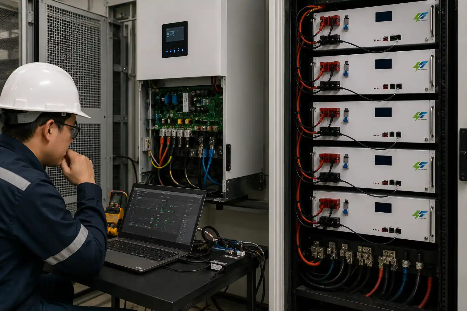
Datasheets are useful for screening, but production qualification should rely on evidence.
The original five-step verification framework is one of the strongest B2B sections in the article and should remain.
Step 1: Review Raw Battery Test Data
Ask for representative charge and discharge data rather than only summary specifications.
Useful records may include:
- Individual cell voltage
- Pack current
- Temperature
- SOC
- Protection events
- Balancing activity
- Charge/discharge limits
- Event timestamps
Evaluate the data together with the actual test conditions.
Step 2: Test the Intended Inverter or PCS
Use the exact hardware and firmware configuration planned for your market or project.
Verify:
- Startup
- Normal charge
- Normal discharge
- Low SOC
- High SOC
- Maximum permitted current
- Communication interruption
- Alarm transmission
- Recovery after fault
- Shutdown behavior
Step 3: Validate Parallel Operation at Planned Scale
Do not validate a large battery system using only one or two packs if the project will ultimately use many more.
Testing should include:
- Different initial SOC levels
- Pack connection sequence
- Addressing
- Current sharing
- Communication stability
- Pack isolation
- Reconnection
- Fault recovery
Step 4: Audit Certification Evidence
Request an evidence package showing which configurations are actually covered.
The package should identify, where applicable:
- Battery model
- Cell type
- BMS hardware revision
- BMS firmware revision
- Electrical protection architecture
- Relevant test configuration
- Certificate or report scope
- Target-market applicability
Avoid relying on unrelated certificates from another battery model or previous hardware revision.
Step 5: Evaluate Engineering Support
A technically mature supplier should be able to discuss more than price and lead time.
Useful questions include:
- Can protection parameters be configured for the intended battery?
- How are protocol changes managed?
- How are firmware versions controlled?
- What happens when an update fails?
- Can the previous firmware be restored?
- How quickly can an integration problem be reproduced?
- Are fault logs available for field analysis?
- How are hardware and firmware changes validated before shipment?
For B2B energy storage procurement, the engineering response after shipment can be as important as the BMS hardware itself.
FAQs
What does BMS mean in a battery?
BMS means Battery Management System. It monitors and manages key battery operating conditions such as cell voltage, current, temperature, SOC, protection limits, balancing, and communication.
What is the main purpose of a battery BMS?
Its main purpose is to keep the battery within defined operating limits while providing the control, estimation, communication, and diagnostic functions required for safe and reliable operation.
Does every lithium battery need a BMS?
Rechargeable lithium battery systems generally require appropriate monitoring and protection. The architecture and complexity of the BMS depend on battery voltage, cell count, power level, application, and certification requirements.
What are the most important BMS specifications?
For energy storage buyers, important areas include measurement performance, protection logic, SOC/SOH estimation, balancing strategy, communication compatibility, parallel operation, fault logging, firmware management, temperature limits, and certification support.
What is the difference between BMS and EMS?
The BMS primarily manages the battery itself.
An EMS operates at a higher system level and may coordinate battery charging and discharging with inverters, loads, renewable generation, tariffs, grid requirements, or site-level operating strategies.
Is active balancing always better than passive balancing?
No.
Active balancing can provide faster energy redistribution and may offer advantages in certain large-capacity or demanding applications. Passive balancing can also be suitable when cell matching, thermal consistency, charging strategy, and balancing time are properly controlled.
How should inverter compatibility be verified?
Compatibility should be tested using the intended inverter or PCS model and firmware together with the actual BMS hardware, firmware, communication interface, and battery configuration.
Does a BMS need its own UL 9540 certification?
UL 9540 applies to the complete energy storage system rather than simply functioning as a universal standalone BMS certificate.
Buyers should verify how the selected BMS and battery configuration fit within the certification scope of the complete product.
What BMS data is useful when diagnosing a field failure?
Useful records include cell voltages, pack current, temperatures, SOC, protection events, balancing status, charge/discharge limits, communication status, and accurate timestamps.
Making BMS Capability Part of Supplier Qualification
For energy storage buyers, a BMS should not be evaluated by one specification such as balancing current, supported protocol count, or maximum parallel quantity.
A stronger evaluation asks whether the complete battery management architecture has been validated for the intended:
- Cell chemistry
- System voltage
- Battery capacity
- Inverter or PCS
- Parallel configuration
- Temperature environment
- Operating profile
- Target market
- Certification pathway
- Service-life expectation
The most reliable evidence comes from test records, compatibility validation, clear firmware control, fault diagnostics, configuration-specific certification documentation, and an engineering team capable of supporting problems after deployment.
For VoltCrave Power, the commercial opportunity is therefore not to claim that one BMS architecture is universally superior.
A stronger B2B position is to demonstrate that the battery system, BMS logic, communication strategy, protection architecture, and test evidence have been matched to the customer’s actual ESS application.
That is what turns BMS capability from an internal component specification into a meaningful supplier-qualification criterion.
Need help matching this topic to a real battery project?
Send your target application, capacity range, certification market, and order plan. VoltCrave can recommend a practical product direction.