
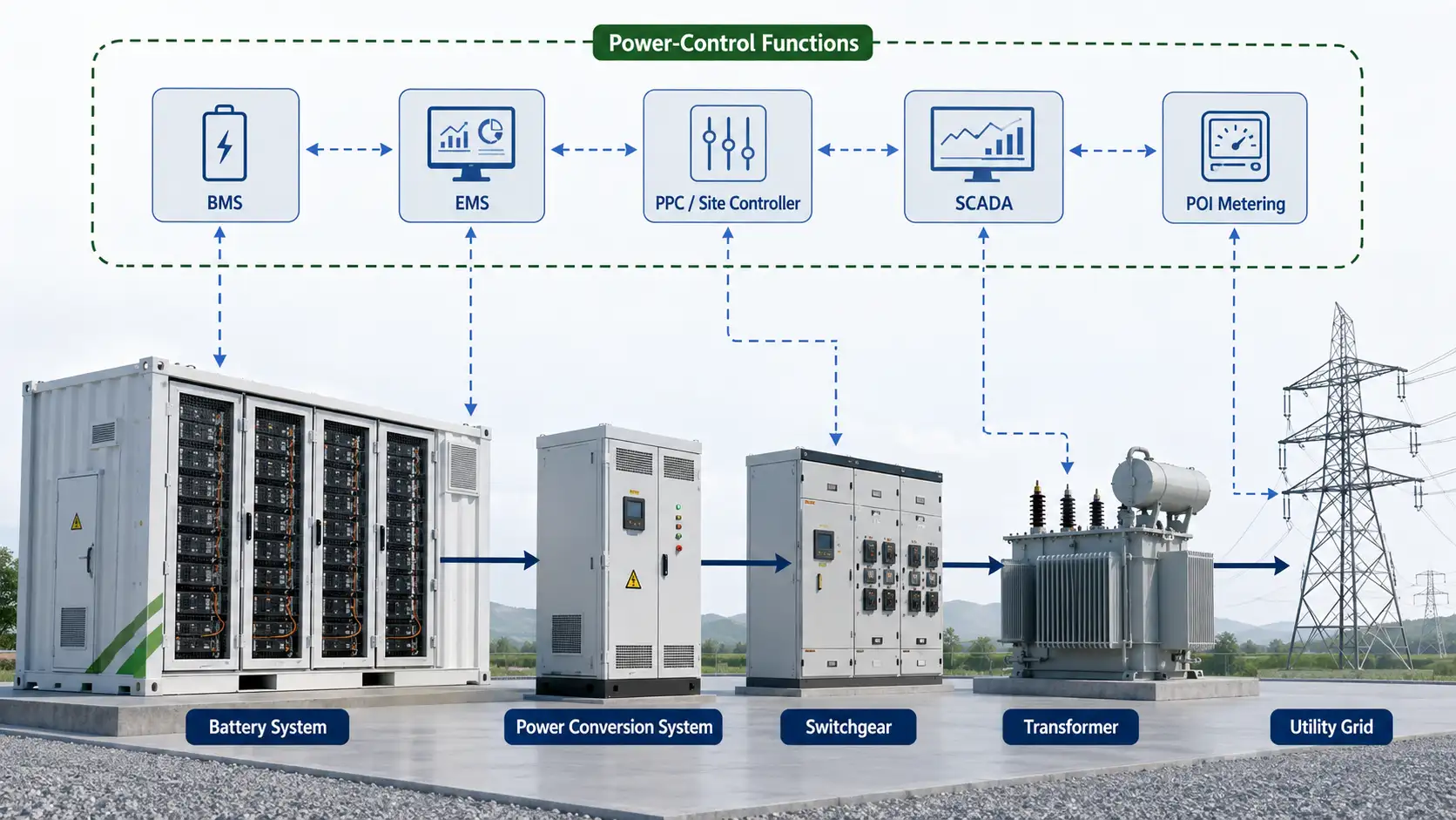
A battery energy storage system can have correctly sized batteries, a capable bidirectional inverter, and a sophisticated energy management system—and still fail to meet project requirements if its power-control responsibilities are poorly defined.
The problem often starts with terminology.
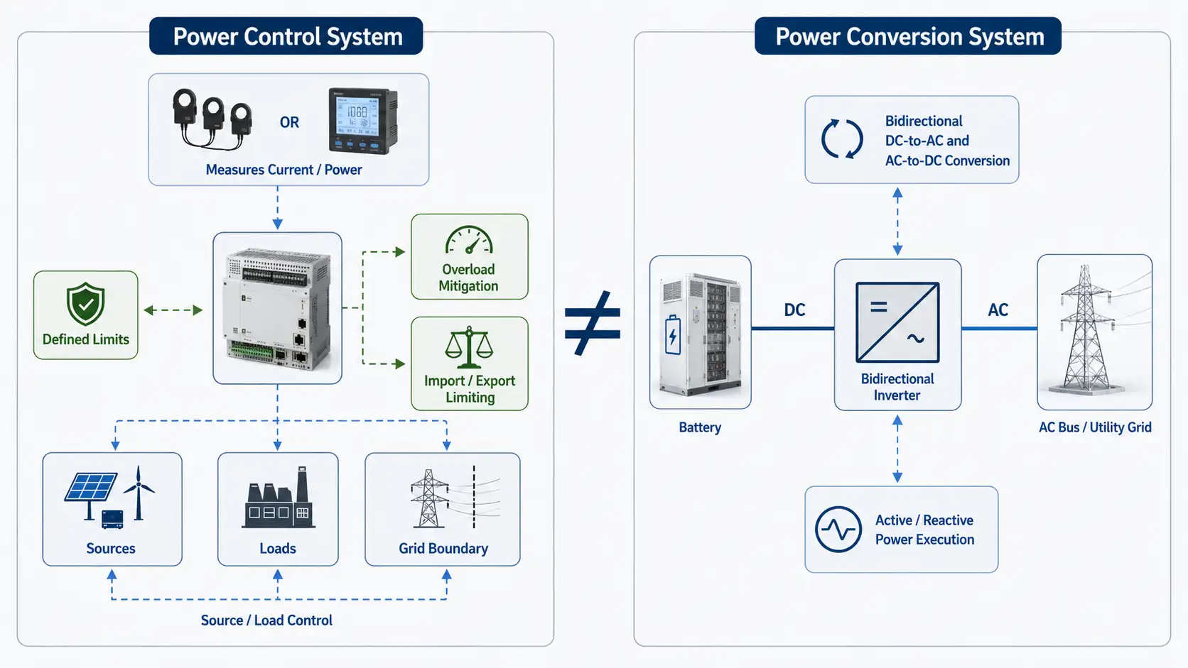
In battery energy storage, PCS commonly means Power Conversion System: the inverter-based equipment that converts power between the DC battery system and the AC electrical system.
In electrical-code and UL terminology, however, Power Control System has a different meaning. UL describes it as a control system that electronically limits or controls current or power within defined limits to mitigate overload conditions.
These two definitions should not be treated as interchangeable.
For BESS engineers, EPC contractors, system integrators, and procurement teams, the more important question is not simply:
What is a Power Control System?
The practical question is:
How should power-control functions be defined, integrated, verified, and assigned across the BMS, Power Conversion System, EMS, plant controller, meters, and site electrical system?
This article addresses that question from an engineering, procurement, integration, and compliance perspective.
Terminology warning: In BESS documentation, “PCS” usually means Power Conversion System. In NEC and UL discussions, “PCS” may mean Power Control System. These are different concepts. Always write the full term in specifications, drawings, test procedures, and contracts.
What Is a Power Control System?
A Power Control System controls or limits electrical current or power so that defined electrical limits are not exceeded.
Depending on the installation, it may supervise or control:
- Electrical sources.
- Loads.
- Feeders.
- Services.
- Busbars.
- Conductors.
- Distributed energy resources.
- EV charging equipment.
- Energy storage systems.
- Combinations of these elements.
The important distinction is that a Power Control System is better understood by what it does than by the physical box that contains it.
UL guidance indicates that a Power Control System may consist of one device or multiple devices operating together. Measurement points may be internal or external, and the power-control function may involve generation equipment, energy storage, loads, circuit controllers, monitoring devices, and remote controllers.
A Power Control System is function-oriented, not necessarily device-oriented.
In one project, the required function may reside primarily in a dedicated controller. In another, the function may be distributed across metering, site controls, inverters, and controlled loads.
The exact architecture, control boundary, and certification scope therefore matter more than the product label.
Power Control System vs Power Conversion System
For BESS buyers, this is the first distinction that must be made.
| System | Primary Role | Typical BESS Function |
|---|---|---|
| Power Control System | Limits or controls current or power within defined boundaries. | Overload mitigation, source/load control, import limiting, and export limiting. |
| Power Conversion System | Converts and conditions electrical power. | Bidirectional DC-to-AC and AC-to-DC conversion between the battery and AC system. |
| Battery Management System | Monitors and protects the battery. | Cell monitoring, SOC/SOH estimation, temperature monitoring, and allowable power limits. |
| Energy Management System | Manages operational strategy. | Charging schedules, dispatch, tariff optimization, and SOC strategy. |
| PPC or Plant Controller | Coordinates plant-level electrical targets. | POI/PCC active-power, reactive-power, voltage, and grid-performance control. |
| SCADA | Supervises and records plant operation. | Telemetry, alarms, historian functions, remote control, and operator interface. |
In BESS documentation, Power Conversion System generally refers to the power-electronic conversion and conditioning equipment that interfaces the battery’s DC system with the AC electrical system.
Depending on the supplier’s design, a Power Conversion System package may also include controls, protection, and auxiliary functions. That does not mean it automatically performs every Power Control System, EMS, or PPC function.
Technical documents should therefore avoid using “PCS” alone when both meanings are possible.
Write the full term at first use:
- Power Control System.
- Power Conversion System.
This simple practice can prevent significant confusion during design reviews, RFQs, commissioning, and warranty discussions.
Power Control System vs EMS, PPC and Site Controller
A second common mistake is to treat the Power Control System, EMS, and PPC as three separate boxes that must always appear in the same architecture.
Real projects are not that standardized.
An EMS may determine that the battery should discharge because electricity prices are high. A plant controller may determine the power required at the point of interconnection. The Power Conversion System executes electrical power conversion. The BMS may simultaneously report that only part of the requested battery power is available because of SOC, temperature, voltage, or another battery constraint.
At the same time, a power-control function may impose another boundary to prevent a conductor, feeder, service, transformer, or other controlled part of the electrical system from exceeding its permitted limit.
These functions may exist in different products, or several functions may be implemented within one site controller or software platform.
The correct question is therefore not:
Which box is the Power Control System?
The better question is:
Which device or combination of devices performs each required function, and what happens when those functions conflict?
How Power Control Fits Into a BESS Architecture
A simplified BESS may contain the following physical power path:
Utility / Grid
      |
POI or PCC Metering
      |
Site AC System / Switchgear
      |------ Loads
      |------ PV or Other DER
      |
Power Conversion System
      |
DC Battery System
      |
Battery Management System
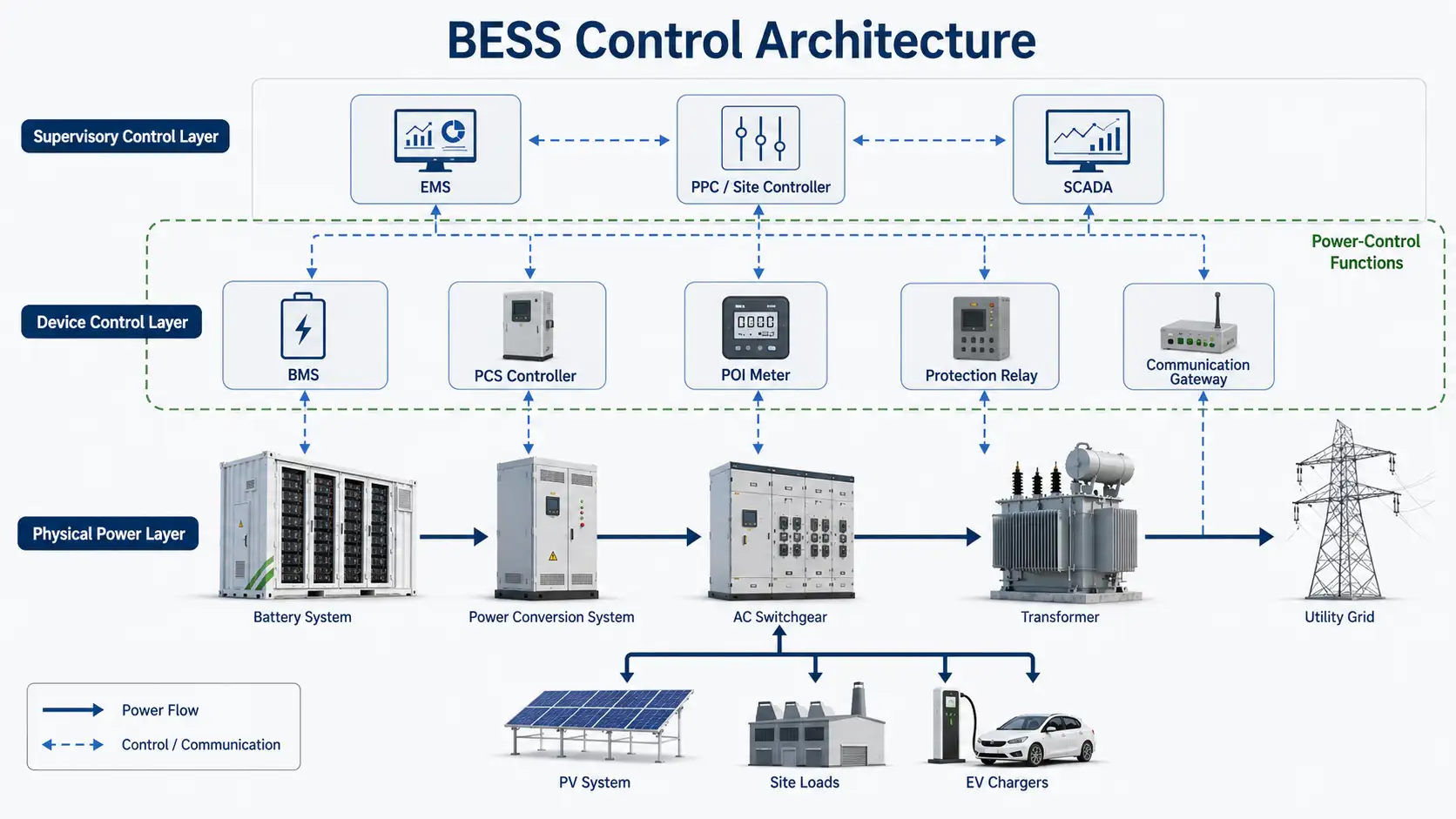
Above and across this physical power path may sit:
- Energy Management System.
- PPC or plant controller.
- Site controller.
- SCADA system.
- Revenue or control meters.
- Protection relays.
- Communication gateways.
- Remote utility controls.
The Power Control System function should not automatically be drawn as another independent box inserted into the power chain.
Instead, engineers should identify its control boundary.
For example:
- What is being limited?
- Is the limit applied to a feeder, service, transformer, busbar, or conductor?
- Is the system controlling grid export or grid import?
- Is an EV charging group included?
- Are multiple sources being coordinated simultaneously?
- Where is the relevant power or current measured?
- Which controller calculates the response?
- Which equipment executes the response?
- What happens if measurement or communications fail?
That functional architecture is more useful than a generic block diagram.
A distributed implementation does not eliminate the need to identify one responsible safety function, one controlled boundary, one set of validated settings, and one documented failure state.
Overload Control and Grid Performance Are Not the Same Thing
One of the biggest technical mistakes in BESS control discussions is placing every electrical-control feature under “Power Control System.” These functions should be separated.
Overload and Capacity-Control Functions
Functions directly related to current and power limits may include:
- Service current limiting.
- Feeder loading control.
- Busbar or conductor loading control.
- Maximum import control.
- Maximum export control.
- Source coordination.
- Load shedding or controlled load reduction.
- EV charging load management.
- PV curtailment where required to maintain a defined limit.
- Coordination of storage and site loads within electrical capacity.
These functions are closely aligned with the Power Control System concept when they are used to maintain defined electrical limits or mitigate overload conditions.
Import and export limiting may form part of a project’s power-control architecture. Whether a particular function falls within UL 3141 scope depends on the applicable code, installation configuration, control function, and listing or evaluation scope.
Grid-Performance Functions
A BESS may also need:
- Active-power control.
- Reactive-power control.
- Power-factor control.
- Voltage regulation.
- Frequency response.
- Ramp-rate control.
- Low-voltage and high-voltage ride-through.
- Grid-following operation.
- Grid-forming operation.
- Black-start capability.
- Plant dispatch.
These are critical BESS requirements, but they should not automatically be described as UL 3141 Power Control System functions.
Depending on the project type and connection level, they may instead involve the Power Conversion System, PPC, utility interconnection agreement, local grid code, UL 1741, IEEE 1547, IEEE 2800, or other project-specific requirements.
Engineering principle: Controlling power does not automatically mean that a product or function is a Power Control System under NEC or UL terminology.
UL 3141 and the 2026 NEC
UL 3141 is particularly important when discussing Power Control Systems in North America. It is titled the Outline of Investigation for Power Control Systems.
UL provides evaluation and certification services related to UL 3141. UL 3141 requirements should be considered in the context of the actual control function, electrical architecture, installation conditions, and applicable code requirements.
The 2026 NEC reorganized Energy Management System requirements into Article 130 and distinguishes traditional energy-management functions from systems performing overload control.
Under the 2026 NEC framework, an EMS that performs overload-control functions covered by the applicable requirements may be required to be listed as a Power Control System. Actual project applicability still depends on the NEC edition adopted by the jurisdiction, the installation configuration, and the interpretation of the authority having jurisdiction.
This distinction is important, but it should not be overstated.
UL 3141 Does Not Mean:
- Every BESS automatically requires UL 3141.
- UL 3141 is the overall BESS safety certification.
- UL 9540 automatically includes UL 3141 approval.
- An EMS is automatically a listed Power Control System.
- Every controller capable of changing kW qualifies as a Power Control System.
Applicability may depend on:
- The required control function.
- The electrical architecture.
- The applicable NEC edition.
- Local code adoption.
- AHJ interpretation.
- The product listing scope.
- The project specification.
- The equipment and installation configuration.
The 2026 NEC may be available nationally, but adoption occurs at the jurisdictional level. Engineers should confirm the legally applicable code edition with the AHJ, project engineer, and relevant local authority.
UL 3141 vs BESS Safety and Interconnection Requirements
These standards and requirements address different technical questions.
| Standard or Requirement | Primary Focus |
|---|---|
| UL 3141 | Power Control Systems and associated power/current control safety functions. |
| UL 9540 | System-level safety of energy storage systems and equipment. |
| UL 9540A | Test method for evaluating thermal runaway fire propagation behavior. |
| UL 1973 | Stationary batteries and battery-system safety. |
| UL 1741 | Inverters, converters, controllers, and interconnection equipment used with distributed energy resources. |
| IEEE 1547 | Distributed energy resource interconnection and interoperability with distribution systems. |
| IEEE 2800 | Transmission and sub-transmission interconnection requirements for inverter-based resources. |
| NFPA 855 | Installation of stationary energy storage systems. |
| NEC and Local Electrical Code | Electrical installation requirements adopted by the applicable jurisdiction. |
UL 9540 addresses system-level ESS safety and includes equipment and system functions such as charging, discharging, protection, controls, and communication among devices.
UL 9540A, by contrast, is a test method used to evaluate thermal runaway fire propagation behavior. It should not be described simply as another product certification.
UL 1741 applies to inverters, converters, controllers, and interconnection equipment used with distributed energy resources.
A professional procurement specification should therefore ask:
Which exact system or component is evaluated to which requirement, and what configuration does that evaluation cover?
That question is more useful than asking only:
Is the system UL certified?
What Engineers Should Specify Before Procurement
A good RFQ should define the operating problem before specifying a controller.
1. Project Information
- Project country and jurisdiction.
- BESS power rating in MW.
- BESS energy capacity in MWh.
- AC voltage.
- System frequency.
- POI or PCC arrangement.
- Transformer configuration.
- Site load profile.
- PV or other generation capacity.
- Operating modes.
- Interconnection constraints.
- Target commissioning date.
2. Controlled Electrical Boundary
State exactly what must be protected or controlled:
- Utility service.
- Feeder.
- Transformer.
- Busbar.
- Conductor.
- POI export.
- Site import.
- EV charging capacity.
- Generation output.
- Multiple DER sources.
Without this boundary, “power control” is too vague to engineer or price accurately.
3. Required Control Functions
Define whether the project requires:
- Maximum import control.
- Maximum export control.
- Zero-export operation.
- Feeder loading management.
- Load control.
- Source curtailment.
- Peak-demand limiting.
- Coordinated PV and BESS operation.
- EV charging coordination.
- Plant-level power targets.
Separate mandatory safety or capacity-control functions from optional optimization functions.
4. Dynamic Performance
Do not copy arbitrary response-time or accuracy numbers from another project.
Instead, define:
- Required response time.
- Control accuracy.
- Permitted overshoot.
- Ramp behavior.
- Measurement update rate.
- Settling criteria.
- Test conditions.
- Operating temperature and SOC range.
- Available battery power during testing.
Performance requirements should be derived from the actual electrical constraint, interconnection requirement, and control objective.
A control-accuracy requirement for a commercial dispatch function is not necessarily the same as the protective margin required for overload mitigation.
Communication Protocols Do Not Guarantee BESS Interoperability
A supplier may claim support for:
- Modbus TCP.
- Modbus RTU.
- CAN.
- DNP3.
- IEC 61850.
- OPC UA.
- Ethernet.
- Application programming interfaces.
That is useful, but insufficient.
The harder questions are:
- Which register contains available charge power?
- Which controller owns the final active-power command?
- How are signed values defined?
- What are the scaling factors?
- What byte order is used?
- How are quality flags represented?
- What happens when data becomes stale?
- How frequently is the measurement updated?
- What time source is used?
- How are firmware-version dependencies controlled?
Two systems can both support Modbus TCP and still fail to exchange the required signals correctly.
The procurement target should be a verified interface, not a list of protocol logos.
The Interface Responsibility Matrix
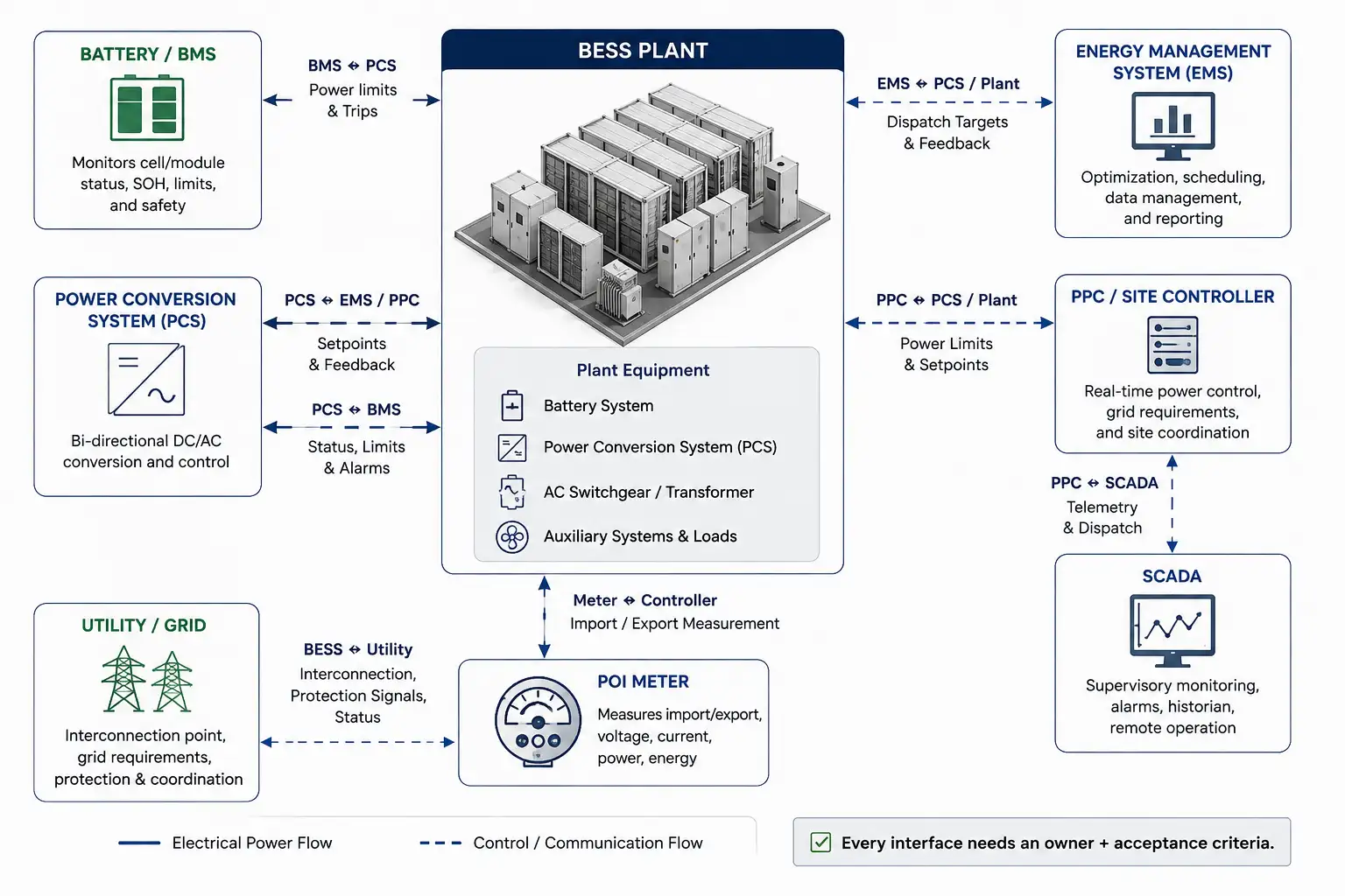
Every complex BESS project should assign responsibility for critical interfaces before commissioning.
| Interface | Responsibility to Define | Acceptance Evidence |
|---|---|---|
| BMS ↔ Power Conversion System | Available charge/discharge limits, trips, and status. | Signal test and derating test. |
| Power Conversion System ↔ EMS/PPC | Setpoints, status, feedback, and command priority. | Command and response verification. |
| POI Meter ↔ Controller | Real-time import/export measurement, polarity, and quality. | Scaling, polarity, and loss-of-signal test. |
| PPC ↔ SCADA | Dispatch, telemetry, alarms, and operator controls. | Point-to-point test. |
| Controller ↔ Loads/DER | Curtailment, load-control, and source-coordination commands. | Functional test. |
| BESS ↔ Utility | Interconnection behavior, telemetry, and dispatch interface. | Project-specific acceptance test. |
The matrix should answer one uncomfortable but essential question:
When the plant fails to achieve the requested result, which party owns the problem?
That responsibility should be reflected in the EPC contract, supply agreement, integration scope, and warranty terms—not left to informal coordination during commissioning.
Control Priority Must Be Defined Before Commissioning
Consider a simple example.
The EMS requests maximum battery discharge. At the same time:
- The BMS reduces allowable discharge power.
- The PPC requests reactive-power support.
- A site import/export controller is enforcing a limit.
- An operator has issued a manual command.
Which request wins?
If priority is not defined, different control loops can compete or produce unpredictable results.
A procurement specification should document the priority assigned to:
- Personnel and equipment protection.
- Battery safety protection.
- Mandatory electrical capacity limits.
- Grid and interconnection requirements.
- Battery dynamic operating limits.
- Plant dispatch.
- Economic optimization.
- Operator overrides.
A possible project-specific hierarchy might look like this:
| Priority | Function | Typical Authority |
|---|---|---|
| 1 | Personnel and equipment protection | Protection systems and BMS safety protection |
| 2 | Mandatory electrical capacity limit | Power Control System function |
| 3 | Grid/interconnection requirement | PPC, site controller, or utility interface |
| 4 | Battery dynamic operating limits | BMS and battery controls |
| 5 | Plant dispatch target | EMS and operator |
| 6 | Economic optimization | EMS |
This is an example for discussion, not a universal mandatory hierarchy. The actual priority logic must be confirmed for the specific project.
Failure Behavior Matters More Than Normal Operation
Most vendor demonstrations show what happens when everything works. Good engineering also asks what happens when the system does not work normally.
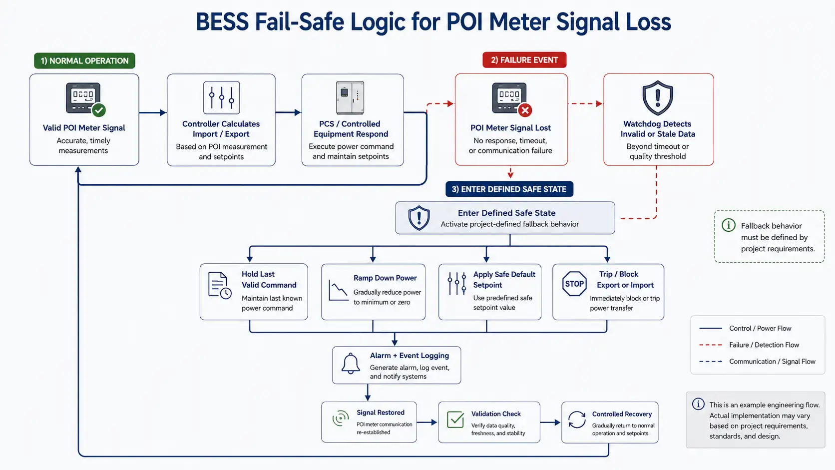
POI Meter Signal Loss
Potential risk: The controller no longer knows the actual grid import or export level.
Specify:
- How meter loss is detected.
- Which measurement-validity rules apply.
- Whether the controller holds the last command, ramps down, reverts to a safe value, or trips.
- How quickly the event is alarmed.
- How recovery is handled.
- How the event is logged.
BMS Power Derating
Potential risk: The plant receives a 1 MW command while the battery currently permits only 650 kW.
Specify:
- How available power is communicated.
- Which controller clips the command.
- Whether the unmet command is alarmed.
- Whether the event is logged.
- Whether other BESS blocks redistribute the requirement.
Controller Communication Loss
Potential risk: The Power Conversion System continues operating from an outdated setpoint.
Specify:
- Watchdog behavior.
- Stale-data timeout.
- Fallback state.
- Autonomous local behavior.
- Restart procedure.
- Operator notification.
Meter Scaling or CT Polarity Error
Potential risk: A controller attempting to reduce export could unintentionally increase it.
Commissioning should verify:
- CT direction.
- Phase mapping.
- Scaling.
- Signed power convention.
- Real and reactive power values.
- Meter-to-controller consistency.
Firmware Mismatch
Potential risk: A software update changes registers, priorities, or device behavior.
Require:
- Approved firmware versions.
- Compatibility matrix.
- Change-control procedure.
- Rollback capability.
- Release documentation.
- Configuration backup.
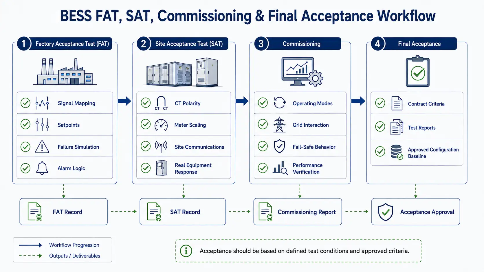
What Should Be Tested During FAT and SAT?
Power-control functionality should not be accepted only because the HMI displays the correct screen.
Factory Acceptance Testing
FAT should verify, where applicable:
- Complete signal mapping.
- Control setpoints.
- Command priorities.
- Measurement scaling.
- Import and export limiting logic.
- Simulated meter failure.
- Communication-loss behavior.
- Simulated BMS derating.
- Controller restart behavior.
- Alarm generation.
- Data logging.
- Manual and automatic mode transitions.
Site Acceptance Testing
SAT should verify:
- Actual CT and meter orientation.
- Site network communication.
- Real equipment response.
- Transformer and switchgear assumptions.
- POI measurement.
- Utility-facing signals.
- Load interaction.
- PV interaction.
- Operating-mode transitions.
- Site-specific fail-safe states.
Performance testing should answer:
Did the plant meet the contracted requirement under the defined test condition?
A result without a defined test condition is difficult to enforce contractually.
Questions to Ask a BESS Controls Supplier
- What exact electrical boundary does your solution control?
- Which device has final authority when EMS, PPC, BMS, and site limits conflict?
- Which functions are executed by the controller, Power Conversion System, EMS, and BMS?
- What happens when the POI meter signal is lost?
- What happens when the BMS suddenly reduces available charging or discharging power?
- Can you provide the complete signal list, register map, and communication interface document before FAT?
- Which functions and hardware combinations are included in each applicable certification or listing?
- What installation conditions or configuration limits apply to that listing?
- What FAT and SAT procedures will demonstrate each guaranteed control function?
- Who owns integration responsibility after commissioning?
- How are firmware updates, parameter changes, and configuration backups controlled throughout the project life?
A supplier that can answer these questions clearly is providing more useful information than one that only advertises “smart EMS” or “intelligent control.”
Common Power-Control Procurement Mistakes
Mistake 1: Confusing the Two Meanings of PCS
Always distinguish Power Control System from Power Conversion System.
Mistake 2: Assuming a Protocol Means Compatibility
“Supports Modbus” does not prove that two products can exchange the required signals correctly.
Mistake 3: Asking Whether the Product “Has UL”
Certification and listing should be evaluated by:
- Standard or requirement.
- Product.
- Model.
- Configuration.
- Function.
- Installation conditions.
- Listing scope.
Mistake 4: Treating UL 9540A as Product Certification
UL 9540A provides test information about thermal-runaway fire propagation. It is not interchangeable with UL 9540 system certification.
Mistake 5: Evaluating Only Rated Power
A nameplate MW rating says little about:
- Control performance.
- Integration quality.
- Failure behavior.
- Availability.
- Data quality.
- Commissioning effort.
- Warranty limitations.
Mistake 6: Ignoring Responsibility Boundaries
Multi-vendor systems create commercial risk when no contract clearly states who owns each interface.
Mistake 7: Selecting on CAPEX Alone
A lower-cost controller or integration package can become expensive if it causes:
- Commissioning delays.
- Repeated site visits.
- Interoperability problems.
- Undocumented firmware changes.
- Poor fault diagnostics.
- Grid-acceptance delays.
- Long troubleshooting cycles.
The correct comparison is not only purchase price. It is total integration and lifecycle risk.
How to Evaluate a BESS Power-Control Solution
Instead of using a price-first comparison, buyers should evaluate the following six areas.
| Evaluation Area | Key Question |
|---|---|
| Functional Fit | Does the solution perform the required import, export, loading, or plant-control function? |
| Electrical Fit | Does the architecture match the service, feeder, transformer, POI, and DER configuration? |
| Integration Fit | Are BMS, Power Conversion System, meters, EMS, PPC, and SCADA interfaces defined? |
| Compliance Fit | Are applicable listings, standards, and interconnection requirements identified? |
| Verification Fit | Can important functions be demonstrated through FAT, SAT, and commissioning testing? |
| Lifecycle Fit | Who supports firmware, backups, configuration management, spare hardware, and expansion? |
The strongest solution is rarely the one with the longest feature list. It is the one whose behavior can be specified, tested, and contractually understood.
Information to Provide Before BESS System Design
For commercial, industrial, and utility-scale BESS projects, control architecture cannot be separated from system sizing.
At minimum, provide:
- Project country and jurisdiction.
- Site voltage.
- System frequency.
- BESS target MW.
- BESS target MWh.
- Transformer rating.
- Maximum site demand.
- Load profile.
- PV or wind capacity.
- Grid export limit.
- Grid import limit.
- Required backup duration.
- Operating modes.
- Interconnection requirements.
- Available single-line diagram.
- Required communication protocols.
- Target commissioning date.
This allows engineers to determine whether the requirement is primarily:
- Storage sizing.
- Power Conversion System sizing.
- EMS dispatch.
- POI control.
- Electrical capacity management.
- Export limitation.
- Microgrid control.
- Or a combination of these functions.
Power Control Must Be Evaluated as Part of the Complete BESS
The most important procurement principle is simple:
A Power Control System should not be evaluated as a standalone device. In a BESS project, it should be evaluated as a defined set of control functions, interfaces, failure behaviors, and compliance responsibilities across the complete electrical system.
A high-quality BESS design connects:
Battery
  |
BMS
  |
Power Conversion System
  |
EMS / PPC / Site Controls
  |
Metering and SCADA
  |
Switchgear and Transformer
  |
POI / Utility
However, this diagram does not mean that one product automatically owns every control responsibility.
The exact architecture may vary. The requirement for predictable system behavior does not.
Engineering a Project-Ready BESS Control Architecture
For commercial, industrial, and grid-scale storage projects, VoltCrave Power reviews battery capacity, Power Conversion System rating, transformer and grid interface, load profile, PV or other DER configuration, operating strategy, and control requirements before recommending a system architecture.
The appropriate control responsibilities, communication interfaces, certification scope, and commissioning tests should be defined from those project inputs rather than inferred from a product label.
An integrated BESS should not be assumed to have UL 3141 Power Control System certification unless the exact relevant configuration, function, and listing have been verified.
For project evaluation, buyers should provide:
- BESS capacity.
- Power Conversion System power rating.
- Grid voltage.
- Transformer rating.
- Load profile.
- PV or other DER capacity.
- Import and export limits.
- Required control functions.
- Project country and jurisdiction.
From there, the electrical architecture, control responsibility, communication interfaces, and verification requirements can be defined before the system is quoted.
Discuss Your BESS Control & Integration Requirements
Share your single-line diagram, BESS capacity, PCS rating, grid voltage, transformer rating, load profile, PV capacity, import/export limits, and required operating modes.
Our engineering team can review the battery, Power Conversion System, EMS, and site-integration requirements for your project.
Frequently Asked Questions
Is a Power Control System the same as a BESS PCS?
No. In BESS terminology, PCS usually refers to the Power Conversion System, which performs DC-to-AC and AC-to-DC power conversion. A Power Control System under UL and NEC terminology controls or limits current or power to defined limits.
Does every BESS require UL 3141?
No. Applicability depends on the control function, installation architecture, adopted electrical code, AHJ requirements, project specifications, and compliance scope.
Is an EMS a Power Control System?
Not automatically. An EMS typically provides energy scheduling and optimization. Under the 2026 NEC framework, an EMS performing specified overload-control functions may fall under Power Control System requirements where the applicable code and installation conditions require it.
Is UL 9540A a certification?
UL 9540A is a test method used to evaluate thermal runaway fire propagation behavior in battery energy storage systems. It should not be treated as equivalent to UL 9540 system certification.
What documents are important when integrating multiple BESS suppliers?
There is no single universal document. At minimum, the project should have an interface responsibility matrix, complete signal list, control-priority logic, failure-state matrix, applicable configuration documentation, and FAT/SAT acceptance criteria.
What should a buyer check before choosing a BESS controls supplier?
Evaluate control functions, electrical boundaries, interoperability, failure behavior, certification scope, commissioning procedures, contractual responsibility, and long-term software support—not only hardware cost or protocol support.
Final Takeaway
Power Control System and Power Conversion System are not interchangeable terms.
For BESS projects, the best procurement process defines the controlled electrical boundary, assigns every control responsibility, verifies communication and failure behavior, confirms the applicable listing scope, and tests the complete system under project-specific conditions.
That is how buyers move from a product label such as “smart EMS” or “intelligent control” to a control architecture that can be engineered, commissioned, verified, and supported throughout the project life.
Need help matching this topic to a real battery project?
Send your target application, capacity range, certification market, and order plan. VoltCrave can recommend a practical product direction.