Power outages are rarely just an inconvenience for telecom sites, server rooms, UPS systems, and commercial facilities. An undersized backup battery shortens the actual runtime of critical equipment, while an oversized battery bank increases rack space, installation complexity, and project cost without necessarily solving the real system constraints.
Therefore, selecting a server rack battery should start from the required load and backup duration, rather than simply choosing the battery with the highest Ah rating.
A properly designed rack-mounted battery backup system must consider: nominal energy, usable battery capacity, continuous and peak current, BMS limits, UPS/inverter compatibility, recharge capability, physical rack space, and future expansion plans.
For projects evaluating 48V server rack batteries, 51.2V LiFePO4 batteries, or higher-capacity 200Ah/300Ah modules, the following process provides a practical framework for system selection.
Start With the Load, Not the Battery Capacity
The first question should not be:
How many amp-hours should the battery have?
A better question is:
How much power must remain available, and for how long?
A telecom cabinet may require several hours of backup, while a UPS protecting servers may only need to bridge short interruptions, wait for a generator to start, or support an orderly shutdown.
Step 1: Identify the actual continuous load
Total Load (W) = Σ All Critical Loads
Step 2: Calculate the required energy
Required Energy (Wh) = Load (W) × Backup Time (h)
For example, a 2,000W critical load that must operate for 4 hours requires:
2,000 W × 4 h = 8,000 Wh = 8 kWh
However, selecting an 8kWh battery does not automatically guarantee 4 hours of backup. The battery must supply the load through the actual system architecture, and several losses and operating limits still need to be considered.
Nominal Battery Energy Is Not the Same as Usable Backup Energy
One of the most common sizing mistakes is treating the battery’s nameplate capacity as the exact amount of energy available to the load.
Nominal battery energy can be estimated as:
Battery Energy (Wh) = Nominal Voltage (V) × Capacity (Ah)
For example:
- 48V 100Ah → 4.8kWh
- 48V 200Ah → 9.6kWh
- 48V 300Ah → 14.4kWh
These are nominal values. Actual usable backup energy is often lower because the complete system may be affected by:
- Permitted depth of discharge (DoD)
- BMS protection limits
- UPS/inverter/rectifier losses
- Standby consumption
- Cable losses
- Battery temperature and aging
- Project reserve requirements
A useful conceptual relationship is:
Usable Load Energy ≈ Nominal Battery Energy × Usable Battery Fraction × Conversion Efficiency
The values used in this calculation should come from the actual battery and UPS/inverter/rectifier/charger specifications. Do not apply a universal assumption such as 80% or 90% to every project. The appropriate design margin should reflect:
- Required end-of-life (EOL) runtime
- Operating temperature
- Expected load growth
- Redundancy strategy
- Recharge opportunity
- Consequences of a longer-than-expected outage
Telecom DC and UPS AC Systems Should Not Be Sized the Same Way
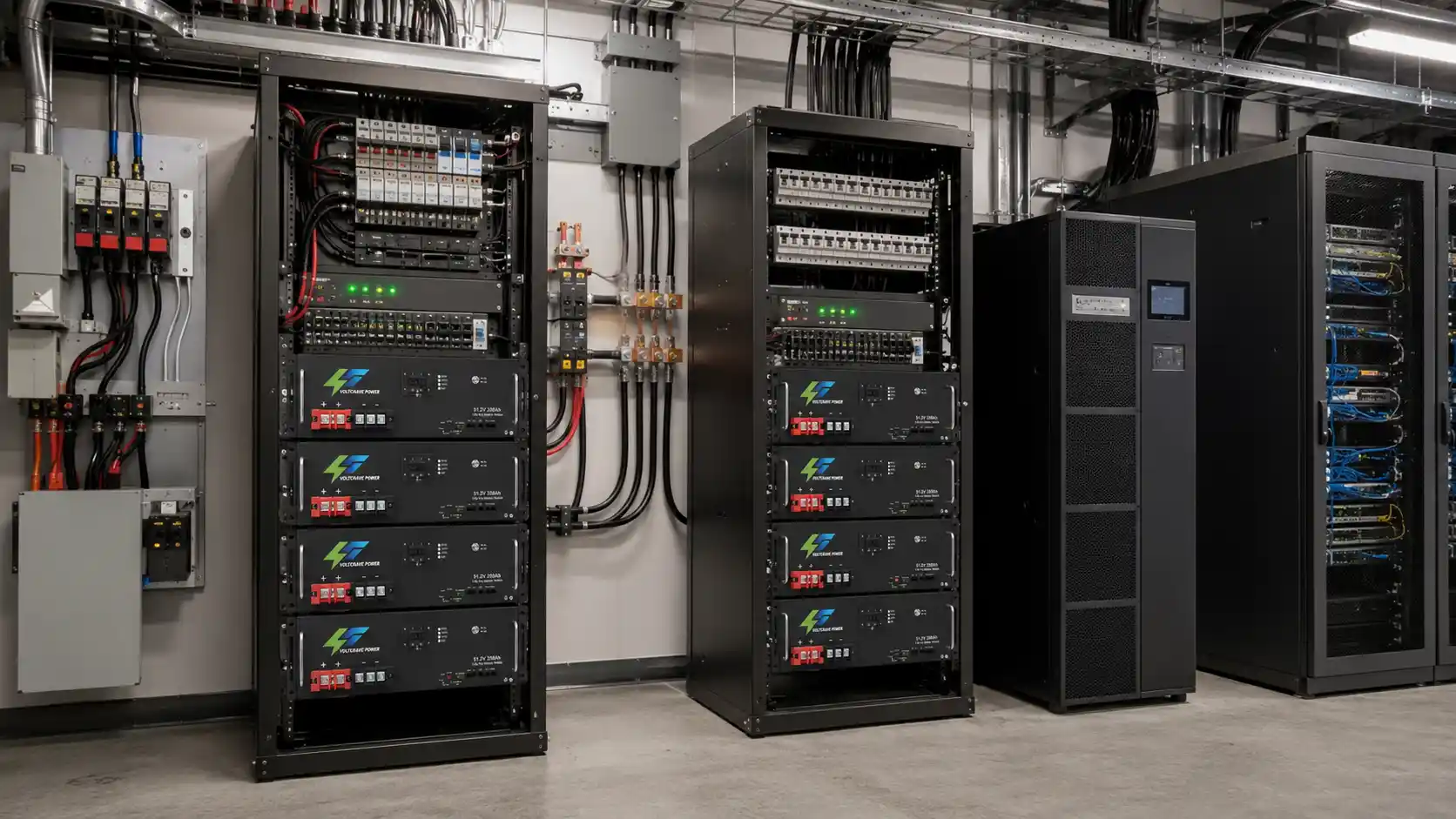
Telecom and UPS installations can use very different power architectures.
Telecom DC Systems
Many telecom sites operate on a 48V-class DC bus:
- Utility power is converted to DC through rectifiers;
- The battery remains connected to the DC system;
- During an outage, the battery may support the telecom load directly.
In this architecture, there may be no DC-to-AC inverter conversion between the battery and the critical load during backup operation.
UPS AC Systems
A conventional server UPS system is different:
- Battery DC energy is normally converted through the UPS inverter to support AC IT loads.
Therefore, do not automatically apply the same conversion-loss model to every rack battery backup project.
- For telecom DC systems, sizing should focus on: actual DC load, bus operating voltage, low-voltage disconnect settings, rectifier and recharge capability, protection devices, and required runtime.
- For AC UPS systems, UPS conversion efficiency, AC load power, battery-side DC current, bypass strategy, and UPS battery-voltage requirements become more important.
How UPS and Inverter Efficiency Affect Backup Runtime
When battery DC energy must be converted to AC, conversion losses increase the battery energy required.
A practical calculation is:
Required Battery Energy = Required Load Energy ÷ Conversion Efficiency
If the load requires 8kWh of AC energy, the battery generally needs to supply more than 8kWh from the DC side.
The correct efficiency should come from the inverter or UPS data at the expected operating load. Efficiency is not necessarily identical at every load level. The UPS or inverter itself may also consume power while operating. For long-duration backup applications, standby or self-consumption should be included rather than ignored.
A Practical Rack Battery Sizing Example
Consider a server system with:
- Critical load: 3kW
- Required backup time: 2 hours
The load requires:
3 kW × 2 h = 6 kWh
Assume (for this example only) that the UPS operates at 93% efficiency at the target load:
6 kWh ÷ 0.93 ≈ 6.45 kWh
If the project design allows 90% of nominal battery energy to be used:
6.45 kWh ÷ 0.90 ≈ 7.17 kWh
So the initial battery-sizing requirement is approximately 7.17kWh of nominal capacity, before adding any project-specific allowance for temperature, aging, future load growth, redundancy, or extended outage risk.
These percentages are examples only. Actual sizing must use the specifications of the battery and UPS selected for the project.
Capacity is only half of the calculation.
At 51.2V nominal battery voltage and 93% conversion efficiency:
Required DC Current ≈ 3,000 W ÷ (51.2 V × 0.93) ≈ 63 A
The battery system must therefore provide both sufficient energy and sufficient continuous current.
This illustrates the key difference:
- kWh determines how long the system can operate.
- Current capability determines whether the battery can support the load at that moment.
When Does a Higher-Capacity Module (e.g., 48V 300Ah) Make Sense?
A 48V 300Ah rack-mount lithium battery represents a much larger energy block than a typical 48V 100Ah module:
48 V × 300 Ah = 14.4 kWh (nominal)
before usable-energy and system-loss factors are applied.
A higher-capacity module can make sense when the project requires:
- Longer backup duration
- Higher stored energy with fewer battery units
- Reduced module count
- Simpler rack organization
- Fewer parallel connections
However, 300Ah is not automatically the best option for every installation. Several smaller modules may provide:
- Easier handling and installation
- Staged expansion
- Module-level replacement
- Better redundancy
The correct choice depends on the complete system architecture rather than Ah alone.
One 300Ah Rack Battery or Three 100Ah Batteries?
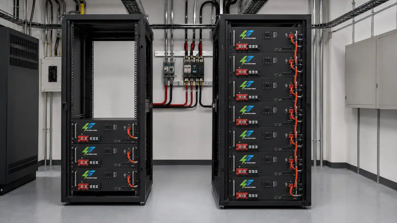
In simple nominal-energy terms:
- 3 × 48V 100Ah = 14.4kWh
- 1 × 48V 300Ah = 14.4kWh
But these two architectures are not necessarily equivalent from an engineering or procurement perspective.
Advantages of multiple smaller modules:
- Easier to transport, install, and replace
- Can be expanded in stages
- If the system architecture permits isolating a single module, part of the total capacity may remain available during service
Trade-offs:
- Additional cabling and connections
- More BMS communication nodes
- More rack positions
- More complex current-sharing considerations
Advantages of a single larger module (200Ah/300Ah):
- Fewer battery units
- Simpler DC cabling, communication-node management, installation, and rack organization
Trade-offs:
- Greater module weight and higher rack-support requirements
- More difficult replacement procedures
- Greater capacity loss if the single module is removed from service
48V Server Rack Battery vs 51.2V LiFePO4 Rack Battery
Another common point of confusion is the difference between a “48V server rack battery” and “51.2V LiFePO4 rack-mounted batteries.”
Voltage labels alone should not be used to determine compatibility.
LiFePO4 cells commonly have a nominal voltage of approximately 3.2V. A 16-cell series configuration therefore has a nominal voltage of:
16 × 3.2 V = 51.2 V
This is one reason 51.2V LiFePO4 batteries are commonly used in systems described broadly as 48V-class battery platforms.
But this does not mean every 51.2V battery can automatically operate with every device labeled 48V.
Before connecting the battery to an inverter, UPS, rectifier, or charger, verify:
- Nominal voltage and actual operating-voltage range
- Charging requirements
- Low-voltage cutoff
- Continuous and peak discharge current
- BMS protection limits
Where closed-loop communication is required, also confirm:
- CAN or RS485 interface
- Communication protocol and cable definition
- Firmware support
- Battery addressing requirements
A “48V” label is a system classification—not a compatibility guarantee.
Current Demand Can Be Just as Important as Energy Capacity
Backup duration determines the amount of energy required. It does not determine whether the battery can deliver the required power.
For AC loads supplied through an inverter or UPS, a better first estimate of DC current is:
Required DC Current ≈ Load Power ÷ (Battery Voltage × Conversion Efficiency)
For final verification, current should also be checked at the lowest expected operating voltage rather than relying only on nominal battery voltage. For the same power demand, DC current increases as battery voltage falls.
This means battery selection must verify more than Ah or kWh. The battery must have adequate continuous discharge capability, the BMS must allow the required current, and the system must tolerate any short-duration peak demand associated with the actual load.
The DC cables, connectors, protection devices, and busbars must also be designed for the required current. Simply increasing battery capacity does not automatically solve a current-delivery limitation.
BMS Limits Can Reduce Available Backup Power
Modern rack-mounted lithium-ion batteries use a battery management system (BMS) to monitor and protect the battery. The BMS may supervise:
- Cell voltage and battery voltage
- Current
- Temperature
- Charging and discharging conditions
For backup applications, one of the most important parameters is the permitted discharge current.
If the connected load demands more current than the battery or BMS allows, protection may activate even though considerable stored energy remains.
This creates a fundamental distinction:
- Capacity determines potential runtime.
- Current capability determines whether the load can actually be supported.
Both must be checked before the battery system is selected.
Peak Loads and Startup Current Need Separate Verification
Average power consumption is not always the highest power the battery system must support.
Server and network equipment may have relatively stable loads, but other equipment connected to the same backup system can behave differently:
- Cooling equipment, pumps, compressors, fans
- Motor-driven auxiliary equipment
- Some power electronics
These loads can create temporary startup or transient demand above their normal running power.
Where these loads are present, verify their actual startup or surge requirements separately from the energy calculation. A battery bank can have enough kWh for the required runtime and still experience a protection event if the battery, BMS, inverter, UPS, or DC distribution system cannot support the temporary current demand.
Parallel Rack Batteries Require More Than Matching Voltage
When one module cannot provide enough capacity or current, additional rack batteries may be connected in parallel where the product and system architecture permit it. But expansion should be planned before installation.
A multi-battery system requires verification of:
- Maximum supported parallel quantity
- Model compatibility
- Cable sizing
- Current-sharing architecture
- Busbar capacity
- Individual module protection
- BMS addressing and master/slave communication (where applicable)
- Inverter communication
- SOC consistency
- Future replacement strategy
Do not assume that any number of batteries with the same nominal voltage can simply be connected together. The supported parallel architecture should be confirmed from the actual battery, BMS, inverter, UPS, or rectifier documentation.
This is particularly important when planning future expansion. A project that starts at 10kWh but may later require 30kWh or 40kWh should consider rack space, cable capacity, busbar capacity, BMS communication, and supported module count at the beginning of the project.
Rack Space Should Be Checked Before Ordering the Battery
Electrical compatibility is only part of server rack battery selection. The product must physically fit the cabinet and be maintainable once installed.
Important checks include:
- Rack width, module height in U
- Cabinet depth, module depth
- Battery weight, cabinet load rating
- Rail or shelf support
- Cable access, breaker access
- Airflow and service clearance
- Module-removal space
This becomes more important as battery capacity increases. A higher-capacity module can look attractive electrically but may create mechanical problems if the cabinet is too shallow, rack loading is insufficient, or maintenance access is restricted.
For commercial projects, cabinet drawings and battery dimensions should be reviewed together with the electrical datasheet before purchasing.
How to Size Rack Battery Backup for Telecom Systems
Telecom backup commonly prioritizes:
- Long runtime
- System reliability
- Predictable DC performance
- Compact rack installation
- Rapid recharge after an outage
Many sites use a 48V-class DC architecture in which the battery supports the DC bus directly rather than feeding an AC inverter.
For these projects, determine:
- Actual DC site load
- Required outage duration
- Peak current
- Battery voltage range
- Low-voltage disconnect settings
- Rectifier and recharge capability
- Available cabinet space
- Environmental conditions
- Required redundancy
Recharge time is particularly important for remote sites. A battery bank may survive one outage but still be inadequate if the charging system cannot restore sufficient energy before another interruption occurs.
Solar-supported telecom sites should also consider available PV energy and seasonal charging conditions.
How to Size Rack Battery Backup for UPS Systems
UPS projects can have very different backup objectives:
- A short-bridge system may only need battery support until a generator starts or utility power returns.
- An extended-runtime system may need the battery itself to maintain critical loads for hours.
These requirements can result in very different battery sizes even when the UPS rating is identical.
UPS systems are also commonly specified in both kVA and kW. Battery-energy calculations should be based primarily on the actual real-power load in kW, while the UPS must still remain within both its kVA and kW operating limits.
Where power factor is relevant:
kW = kVA × Power Factor
Do not size the battery bank directly from the UPS nameplate kVA rating. The actual protected load, backup duration, UPS efficiency, and battery-side current are more important.
How to Size Rack Battery Backup for Server and IT Loads
Server environments often have relatively predictable loads, but actual measurement is still preferable to assumptions.
Do not simply add the maximum nameplate rating of every server power supply. Where possible, determine the real operating load using:
- UPS monitoring
- Intelligent PDU data
- Server management systems
- Appropriate electrical measurement
The protected load may include servers, storage equipment, network switches, routers, monitoring systems, and other critical infrastructure.
Then determine which loads genuinely need battery support. Separating critical from non-critical loads can:
- Reduce the required battery capacity
- Simplify system design
- Lower project cost
- Create a clearer path for future expansion
Should You Add Extra Capacity for Future Expansion?
Future growth should be considered during the original design, but adding an arbitrary percentage of extra battery is not necessarily the best solution.
Instead, identify:
- Expected load growth and expansion schedule
- Supported battery-module count
- Future rack-space requirement
- BMS scalability
- Communication architecture
- Whether cables and busbars can support the additional current
Also consider whether identical or compatible battery modules are expected to remain available when the system is expanded.
A better strategy is to design a clear expansion path rather than simply oversizing the initial battery bank.
Rack Battery Backup Sizing Checklist
| Item | What to Confirm |
|---|---|
| Critical load | Actual watts, kW, or DC current |
| Backup duration | Required minutes or hours |
| System architecture | Telecom DC bus, AC UPS, inverter, or hybrid system |
| Battery voltage | 48V, 51.2V, or required operating range |
| Nominal energy | Voltage × Ah |
| Usable energy | Based on actual product and system limits |
| Continuous current | Must support the operating load |
| Peak demand | Verify transient or startup loads |
| Lowest operating voltage | Recheck maximum DC current at low voltage |
| BMS limits | Charge and discharge current limits |
| UPS/inverter/rectifier | Voltage, current, efficiency, and compatibility |
| Communication | CAN, RS485, and protocol where required |
| Parallel expansion | Maximum supported configuration |
| Rack dimensions | Width, depth, and U height |
| Mechanical load | Battery weight and cabinet support |
| Environment | Temperature and ventilation |
| Recharge capability | Time required to recover after an outage |
| Design reserve | Aging, temperature, redundancy, and load growth |
| Future expansion | Rack, busbar, cable, and communication capacity |
Commercial installations should also verify the electrical, battery-safety, transport, fire-protection, and installation requirements applicable to the target market and project type. These requirements vary by country, application, and local authority.
FAQs
1. How long will a 48V 300Ah rack-mount lithium battery provide backup power?
A 48V 300Ah battery has 14.4kWh of nominal energy, but actual runtime depends on load power, usable battery capacity, system efficiency, temperature, standby consumption, and BMS limits.
2. Can a 51.2V LiFePO4 rack battery work with a 48V inverter?
Often yes in a 48V-class system, but compatibility must be verified through the inverter operating-voltage range, charging settings, low-voltage cutoff, current requirements, and BMS communication.
3. Is one 300Ah rack battery better than three 100Ah batteries?
Not always. A larger module can reduce module count and cabling, while multiple smaller batteries may offer easier handling, replacement, redundancy, and staged expansion.
4. How many server rack batteries can be connected in parallel?
There is no universal number. The limit depends on the battery model, BMS, communication architecture, busbar and cabling design, and the manufacturer’s supported configuration.
5. What should I check before buying a rack-mount battery backup system?
Confirm the actual load, required runtime, battery voltage, usable energy, continuous and peak current, BMS limits, system compatibility, rack dimensions, recharge capability, and future expansion requirements.
Final Selection: Capacity Is Only One Part of the System
The best rack-mount battery backup system is not necessarily the one with the highest Ah rating.
- A 100Ah module may be appropriate where modularity, easier handling, and staged expansion are priorities.
- A 200Ah or 300Ah module may make more sense where longer runtime, fewer battery units, and higher energy capacity per module are required.
The correct choice depends on the complete project:
Load + Runtime + Usable Energy + Voltage + Current + BMS + System Compatibility + Rack Space + Recharge Capability + Expansion Plan
This is particularly important when comparing a 48V 300Ah rack-mount lithium battery with several smaller rack battery modules. Similar nominal energy does not necessarily mean identical current capability, redundancy, maintenance requirements, BMS architecture, cabling complexity, or expansion flexibility.
Need help matching this topic to a real battery project?
Send your target application, capacity range, certification market, and order plan. VoltCrave can recommend a practical product direction.