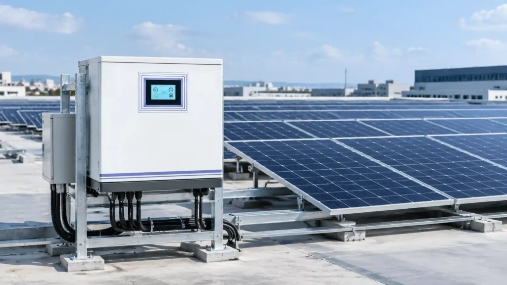
A rooftop array does not care which brand is on the wall. It cares whether the machine behind it accepts 27A on one tracker or 18A, whether nine modules in series survive a cold sunrise, and whether the battery can deliver 645A without the BMS opening.
All three numbers are published. They are simply not the numbers a buyer reads first. What follows is how to judge a three phase solar inverter the way a commercial project needs it judged, using the 18kW and 33kW models in the VoltCrave Power range as the worked example, because their figures make each trade-off visible.
Why a commercial roof forces the three-phase question
Below roughly 10kW, single-phase is the default and nobody argues about it. Above 15kW the arithmetic starts to decide for you. An 18kW load on a 230V single-phase supply draws 78A. The same load spread across three phases at 400V draws 26A per phase, on cable a fraction of the size, through switchgear that costs less and fits in a standard enclosure.
The load side pushes the same way. Chillers, air handling units, pumps, lifts and AC EV chargers are three-phase machines. Supplying them from a single-phase inverter means either a phase balancer or a permanently unbalanced site, and in most markets the utility will not energise a service large enough to make single-phase sensible at this scale.
A three phase solar inverter is also not simply a bigger single-phase one. The topology changes what the machine can be asked to do, so the limits worth checking are different from the ones a domestic job teaches you. For a commercial PV system the question is not whether to use a three phase solar inverter. It is which of the machine’s five published limits binds first on this particular roof, and the rest of this article takes them in the order they usually bite.
The two models, side by side
Both are hybrid machines with a 48VDC battery bus, a three-phase AC input and a three-phase AC output. The 18kW and 33kW three-phase hybrid solar inverter is the three-phase model in the hybrid inverter range, and both ratings share one architecture, differing mainly in how many trackers they carry.
| Parameter | KA18048SS | KA33048SS |
|---|---|---|
| Rated power | 18,000W | 33,000W |
| Peak power | 36,000W | 66,000W |
| Battery voltage | 48VDC | 48VDC |
| AC input | 3 × 380/400VAC, L1+L2+L3+N+PE | 3 × 380/400VAC, L1+L2+L3+N+PE |
| Output | 380VAC ±5%, 50/60Hz ±0.1%, pure sine | 380VAC ±5%, 50/60Hz ±0.1%, pure sine |
| Nominal output current | 3 × 26.9A | 3 × 47.8A |
| MPPT routes | 3 | 6 |
| Max PV input power | 3 × 7,500W | 6 × 5,500W |
| MPPT tracking range | 90–500VDC | 90–500VDC |
| Max PV input voltage | 500VDC | 500VDC |
| Max PV input current | 3 × 27A | 6 × 18A |
| Max PV charge current | 360A | 450A |
| Max AC charge current | 300A | 450A |
| Max total charge current | 360A | 450A |
| Peak efficiency / PF | 0.98 / >0.99 | 0.98 / >0.99 |
| Communication | RS232, BMS, WiFi, dry contact | RS232, BMS, WiFi, dry contact |
| Operating temperature / noise | −10 to 50°C / ≤50dB | −10 to 50°C / ≤50dB |
Two details in that table do most of the work later. The bus is 48V, not 400V. And the per-tracker current limit is lower on the bigger machine, 18A against 27A, which is where most of the array sizing work happens.
Limit 1: at 48V, count amps before you count watts
A 48V bus is convenient for batteries and punishing for current. Divide rated power by nominal voltage and the numbers stop being abstract.
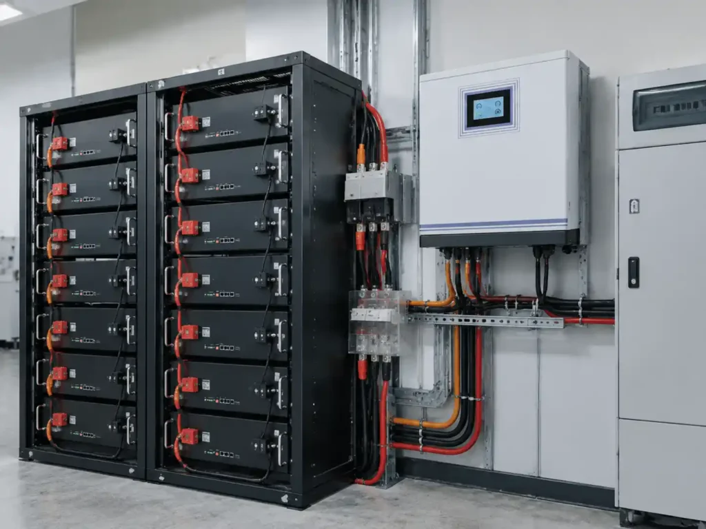
The 18kW model pulls 352A from a 51.2V bank at full load. The 33kW model pulls 645A, or 688A if the bank is sitting at a flat 48V. A 400V-battery machine of the same rating would draw 45A and 83A respectively. That difference is the whole design consequence of the 48V choice.
645A continuous is a busbar, not a cable. It sets the DC breaker or fuse rating, the cross-section and number of parallel runs, the torque spec on every lug, and the number of racks in parallel. It also sets the pre-charge question: closing a breaker into a large bank at 48V produces an inrush that welding-grade contactors dislike, so ask whether the inverter pre-charges the DC link or expects an external pre-charge circuit.
None of that makes the machine wrong. It makes it a fit question. A 48V three phase solar inverter is the natural choice for a site that already runs a 48V rack fleet, for a distributor whose battery line is 48V, and for projects where the battery must be serviceable by telecom-trained staff. It is the wrong choice for a new build that is free to pick a 400V battery and would rather run 83A than 645A.
Limit 2: the tracker current ceiling, not the tracker wattage
Marketing tables quote PV power per tracker. The constraint that actually caps an array is current, and on the 33kW model it is tight.
The 18kW model allows 27A per tracker. The 33kW model allows 18A per tracker across six trackers. Take the 550W monocrystalline module in the VoltCrave Power range: 41.97V at maximum power, 13.11A, 49.95V open circuit. Two strings in parallel on one tracker is 26.2A, which fits 27A with 0.8A to spare and does not fit 18A at all.
That single fact reshapes a design. On the 33kW model each tracker takes one string of these modules, because a second string would exceed 18A. One string delivers 13.11A and about 4.4kWp from eight modules, or 4.95kWp from nine, though the cold check rules nine out on most sites. The published 5,500W per tracker assumes a string running near 306V at 18A, and the extra capacity simply stays unused. Across six trackers the array tops out at 26.4 to 29.7kWp, a DC/AC ratio of 0.80 to 0.90, not the 1.0 the power column suggests.
| Configuration | Modules per tracker | kWp per tracker | Tracker current | Tracker limit used |
|---|---|---|---|---|
| 18kW, 2 strings of 7 | 14 | 7.70 | 26.2A | 97% of 27A |
| 18kW, 2 strings of 8 | 16 | 8.80 | 26.2A | 117% of 7,500W, about 15% clipped at peak |
| 33kW, 1 string of 8 | 8 | 4.40 | 13.1A | 80% of 5,500W |
| 33kW, 2 strings of 8 | 16 | 8.80 | 26.2A | exceeds 18A |
The last row is the mistake to avoid. It looks better on a module count and it is outside the input rating. Two strings per tracker on the 33kW model needs modules at 9A or less, which is a different module class, not a different wiring choice.
Limit 3: the 500V ceiling sets string length, the 90V floor rarely does
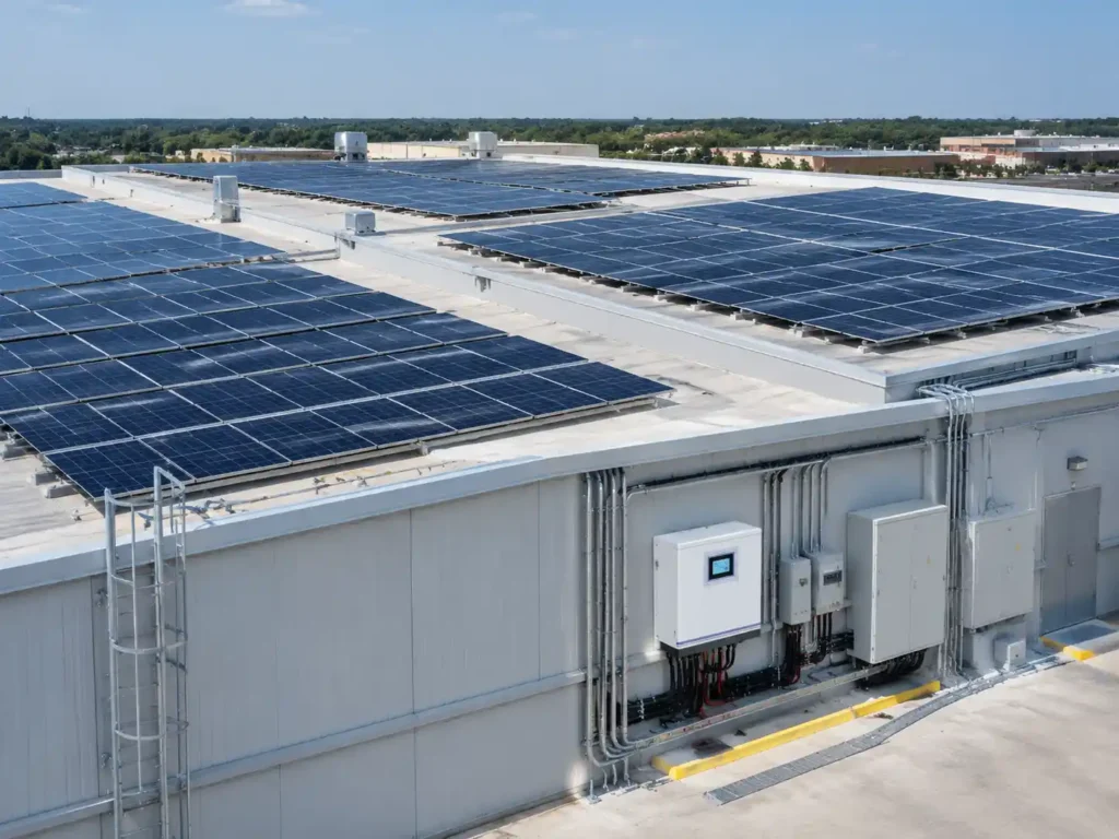
Many three phase solar inverter models start tracking around 120V, which forces four or five 60-cell modules in series before the machine will work at all. This one starts at 90V, so three 550W modules in series, 126V at maximum power, will track. That matters on a commercial roof broken up by plant rooms, skylights and parapets, where a short string on a small plane is otherwise wasted.
The ceiling is the constraint. At 500VDC maximum input, ten modules in series is 499.5V open circuit at 25°C and therefore impossible on any cold morning. Nine modules is 449.6V at 25°C, and the cold check decides the rest.
Open-circuit voltage rises as temperature falls. With a typical monocrystalline coefficient of −0.28%/°C, and a site record low of −10°C, nine modules reach about 494V. That is inside 500V, but the margin is 1.2%, which is not a margin at all once the coefficient is uncertain. Eight modules reach about 439V and leave 12%.
| String length | Vmp at 25°C | Voc at 25°C | Voc at −10°C* | Margin at 500V |
|---|---|---|---|---|
| 7 modules | 293.8V | 349.7V | 383.9V | 23% |
| 8 modules | 335.8V | 399.6V | 438.8V | 12% |
| 9 modules | 377.7V | 449.6V | 493.6V | 1.2%, too thin to design on |
| 10 modules | 419.7V | 499.5V | 548.5V | exceeds the input rating |
* Calculated with a −0.28%/°C Voc coefficient, which is typical for the module class and must be replaced with the coefficient on the actual module datasheet before the design is frozen.
The design rule that follows is simple: take the longest string whose cold-morning open-circuit voltage stays under 500V with at least 5% margin, then check that its current fits the tracker. A 5% rule lands on eight modules with this 550W panel at a −10°C site. Nine only works if the module’s own coefficient and the site’s record low both come back better than assumed, in writing.
Limit 4: the battery is a current device, not an amp-hour figure
Buyers compare bank size in kWh. A three phase solar inverter compares it in amps, and on this product the charge current is the larger number.
450A on the 33kW model, at an absorption voltage around 56.8V, is roughly 25.6kW of charge power. If the cells are rated for 0.5C charge, that current needs at least 900Ah at 48V, about 46kWh, before the inverter is allowed to use its full rating. A 20kWh bank on the same machine would be charged at well over 1C unless the charge current is limited in settings, and someone has to remember to limit it.
Discharge runs the other way. The 33kW model needs 645A of delivered current at 51.2V, so the parallel rack count follows from each rack’s continuous discharge rating, not its capacity. At 100A per rack that is seven racks; at 50A per rack it is thirteen. The rack-mounted LiFePO4 range covers 48V units from 50Ah to 300Ah with a cycle life of 6,000 or more, which is the right shape for this duty, but the continuous current per model has to come from the datasheet rather than from the Ah figure.
Two questions belong in the RFQ, not in the commissioning visit: what continuous charge and discharge current does each rack model carry, and can the inverter’s BMS link enforce a current limit or does it only read state of charge and cell voltage. The communication list on this product reads RS232, BMS, WiFi and dry contact. CAN is not named, and most 48V commercial rack BMS speak CAN, so confirm the protocol before the battery order goes out.
Limit 5: the AC side is 380 or 400V, and nothing else
The output is 380VAC ±5% on a four-wire system, so line-to-neutral is about 219V. That fits European, Australian, Middle Eastern and most Asian commercial services and 50Hz or 60Hz operation. It does not fit a North American 208V three-phase service, and a 480V service needs a 480/400V transformer between the utility and the inverter.
Multiply the published per-phase current by the site voltage before comparing models. At 400V, 26.9A and 47.8A work out to 18.6kW and 33.1kW. At 380V the same currents give 17.7kW and 31.5kW. The nameplate wattage is nominal; the current is what the cable, the breaker and the utility see. That one multiplication is also what tells you whether a three phase solar inverter fits the building, and it is the figure a quotation usually leaves out.
The AC charge figure is the one most often misread. 300A and 450A are DC amps into the battery, not amps drawn from the grid. At 400V three-phase that is roughly 25A and 38A per phase for a full AC charge, so a 63A three-phase supply can feed either model at its maximum charging rate. A generator sized for charging alone needs about 20kVA for the 18kW model and 30kVA for the 33kW model, plus margin for the step load when charging starts.
Peak output is twice rated on both models, 36kW and 66kW. That headroom is real, but the datasheet does not state how long it lasts, so for pump, compressor or chiller starting duty, request the surge curve and compare it with the motor’s starting current, which on a direct-on-line start runs several times its running current.
One worked example: 26kWp on a warehouse roof
Forty-eight 550W modules, 26.4kWp, split across three roof orientations with sixteen modules each. Both options below use the same three phase solar inverter platform, and the difference is entirely in how the array and the load are matched.
33kW model. Six trackers, two per orientation, one string of eight modules on each. Each tracker sees 4.4kWp at 13.1A and 335.8V, with a cold-morning open circuit of about 439V at a −10°C site. The array is 26.4kWp against 33kW of output, a DC/AC ratio of 0.80. One machine covers the whole roof and leaves 33kW of three-phase output for the building load.
18kW model. Forty-two of the same modules, 23.1kWp, three trackers with two strings of seven, and six modules left in the crate. Each tracker sees 7.7kWp at 26.2A, 200W above the 7,500W input rating, which clips 2.7% at peak irradiance and is normal practice. Cold-morning open circuit is 384V, well inside 500V. The DC/AC ratio is 1.28, so the array is worked harder for every kW of inverter capacity bought.
The choice between them is a load question, not an array question. If the building’s daytime load sits near 30kW and the PV is meant to serve it directly, the 33kW model avoids importing at peak, and the 0.80 array ratio is the price of that headroom. If the load is nearer 15kW and the battery is the real destination for the energy, the 18kW model with 23.1kWp produces more per kW of inverter and costs less. The two mistakes are symmetrical: buying 33kW to serve a 15kW load buys stand-by capacity the site will never use, and buying 18kW for a 30kW load guarantees a peak import every afternoon.
What the datasheet does not answer
Five things are missing from the published page, and each one can change a specification.
Grid-connection approval. The compliance list on the product page is battery and cell documentation: IEC 62133-2, UL 1642, UN38.3, RoHS, CE/EMC and MSDS. None of those is an anti-islanding or grid-code approval for the inverter. A three phase solar inverter sold into a commercial project needs that document in its own right, and it cannot be inferred from the battery paperwork. For a grid-parallel project, ask for the inverter’s own certificate and check it against the local code, because the answer differs by market and the document has to exist before the utility will sign off.
Efficiency curve. Peak efficiency of 0.98 says nothing about part-load behaviour, and a commercial array spends most of its hours below 50% of rating. Ask for the weighted efficiency figure used in the local yield model.
IP rating. Not published, so plan an indoor plant room or a sheltered enclosure. Noise is stated at ≤50dB, which suits a plant room and not a sales floor.
Derating above 40°C. The operating range runs to 50°C with no derating table. A plant room at 45°C in summer is normal in the Gulf and in northern Australia, and the available output at that ambient is a design input, not a detail.
Phase imbalance. Line-to-neutral loads at 219V are physically possible on a four-wire output, but the permissible imbalance between phases is not stated. If the site has significant single-phase load, ask before assuming the inverter will carry it.
The RFQ checklist
Send these as questions, not as assumptions, and the quote comes back usable.
- Rated output of the three phase solar inverter at the site’s actual voltage, 380V or 400V, in kW and amps per phase
- Continuous and surge output current, with the surge duration in seconds
- Per-tracker maximum current, maximum power and the resulting DC/AC ceiling for the module chosen
- Maximum PV input voltage confirmed against the cold-morning open-circuit calculation
- Battery continuous charge and discharge current, and the BMS protocol, CAN or RS232
- Whether the inverter pre-charges the DC link or needs external pre-charge
- AC input current per phase at maximum charge rate, for the supply and generator sizing
- Grid-code certificate number and the markets it covers
- Derating curve above 40°C, and the IP rating
- Warranty terms for the inverter and for the battery, stated separately
For an OEM or private-label programme the same list applies with the branding, enclosure and documentation package added, which is what the OEM/ODM service is set up to handle, and a test unit before volume is ordered through the sample evaluation programme.
Commissioning checks that catch most of the faults
Phase rotation. Confirm L1, L2, L3 order at the AC input and at the output. A reversed pair will run a chiller backwards and is the most common three-phase commissioning error.
Neutral and earth. The machine expects L1+L2+L3+N+PE. Confirm the site’s earthing arrangement with the authority having jurisdiction before bonding anything, because the requirement differs between TN and TT systems.
BMS communication before load. Bring the battery link up and confirm the inverter reads state of charge, cell voltage and current limit while the load is still off. A protocol mismatch found at this point costs an hour; found at handover it costs a week.
Charge current limit in settings. Set it to what the bank can accept, not to the inverter maximum. The machine will happily deliver 450A into a bank that should see 200A.
Load bank and imbalance test. Run a balanced load to rated current, then the site’s real single-phase load, and record the imbalance. Compare against the figure the supplier confirmed in the RFQ.
Generator transition. If a generator is part of the design, test the transfer at load and watch the AC input current limit, because charging plus building load can exceed the generator’s rating in the first minutes after transfer.
FAQs
How many 550W panels can the 33kW model take?
Six trackers at 18A each. With a 550W module at 13.11A, each tracker takes one string, eight modules on most sites and nine only where the cold-morning check allows it, so the array lands between 26.4kWp and 29.7kWp. Reaching the full 33kWp needs modules closer to 18A, or two parallel strings per tracker, which this module cannot do within the current limit.
Can it run without a battery?
The published specification defines a 48VDC battery system and does not describe a PV-only or battery-less mode. Treat it as a battery-based hybrid and size the bank as part of the design rather than as an optional extra.
Is it a grid-tie inverter that can export?
The page describes grid operation and solar-grid complementarity but publishes no grid-code or anti-islanding certificate. For an export or grid-parallel project, get the certificate and the utility approval first. For self-consumption with no export, confirm with the supplier whether a CT or export-limiting accessory exists for this model.
What battery bank does the 33kW model need?
At least 645A of continuous discharge capability at 51.2V, and enough capacity that 450A of charge stays within the cells’ charge rate. At 0.5C that is about 46kWh minimum. The rack count follows the per-rack current rating, not the kWh figure.
Will it work on a 208V or 480V service?
No to 208V. The output is 380VAC ±5% and the input is 3 × 380/400VAC. A 480V service needs a 480/400V transformer, and a 208V service is outside the range entirely.
Can two of these run in parallel for a larger site?
Parallel operation is not stated on the product page. For a load above 33kW, ask the supplier directly rather than assuming a parallel kit exists, and treat multiple three phase solar inverter units as separate systems until that is confirmed in writing.
Summary
Choose in this order, and the model picks itself.
First, calculate the DC current at the site’s battery voltage. If 645A is a problem for the DC gear, the bus voltage is the real decision and the model number is secondary. Second, calculate the array against per-tracker current, not per-tracker watts, because that is where a 33kW machine quietly becomes a 26kWp machine. Third, calculate the cold-morning open-circuit voltage for the chosen string length and leave 5% margin under 500V.
Only after those three checks does it make sense to compare price, warranty or brand. A three phase solar inverter that fits the array, the bank and the service voltage is a boring installation. One that fits two of the three is a commissioning visit, a settings workaround and a conversation with the customer about why the array is clipping in March.
Need help matching this topic to a real battery project?
Send your target application, capacity range, certification market, and order plan. VoltCrave can recommend a practical product direction.