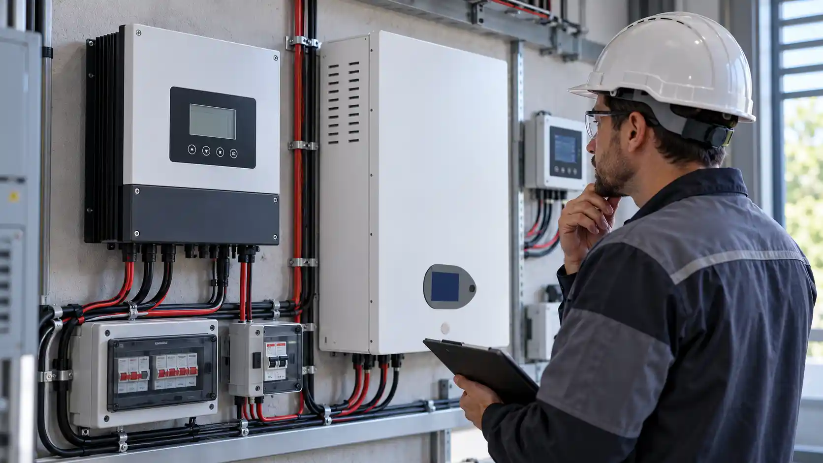
A charge controller that says “float” while the shunt says 70% is not usually broken. It is doing exactly what it was configured to do, on a battery whose definition of full is different from its own.
LiFePO4 makes this gap visible. On lead-acid the voltage curve is steep enough that a controller can infer state of charge from terminal voltage with reasonable accuracy. On LiFePO4 the curve is flat across most of the usable range and then rises sharply at the top, so an MPPT solar charge controller applying the same inference either overshoots or gives up early.
The result is a system that looks healthy on the controller display and underperforms in service. This article works through the five mechanisms that produce it, in the order they are worth checking, and ends with the six lines that should go into a specification so the next build does not repeat it.
Three different numbers are all called “100%”
Before changing any setting, separate the three measurements that get collapsed into one word.
The charge controller decides the battery is full when its absorption phase ends. That happens either when the absorption timer expires or when charge current falls below the tail current threshold. It is a timer plus a current measurement, not a chemical measurement.
The BMS decides on cell voltage and, in most packs, a coulomb count. It will cut charging when the highest cell reaches its limit, and it reports a state of charge from its own model.
A shunt or smart battery monitor counts amp-hours in and out and applies a charge efficiency factor. It is the only one of the three that measures energy rather than inferring it.
When these three disagree, they usually disagree by a predictable amount, and the disagreement is diagnostic. A controller at 100% with a shunt at 70% points at the charge profile or at the sense point. A BMS at 100% with a shunt at 70% points at cell imbalance or a badly calibrated coulomb counter. Same symptom, different repair.
Why the default profile is still a lead-acid profile
Most controllers ship with lead-acid defaults, because most of the installed base is lead-acid. Victron’s public MPPT manual is a useful reference because it documents both sets of defaults rather than hiding them behind a battery-type dropdown.
For lead-acid, that manual specifies an absorption voltage of 14.4V, a float voltage of 13.8V and a tail current of 2A, with absorption time set by a table keyed to the battery voltage at start-up, from one hour at the top of the table to six hours at the bottom. Absorption ends when current drops below the 2A tail current.
For LiFePO4 the same manual specifies 14.2V absorption (28.4V at 24V, 56.8V at 48V), a fixed two-hour absorption, a float voltage given as 13.5V (27V, 54V) in the operation section and 13.2V (26.4V, 52.8V) in the lithium table further down, equalization disabled, temperature compensation disabled, a low-temperature cut-off at 5°C, and a tail current of 0A, with the stated reason that the full absorption time stays available for cell balancing.
That 2A against 0A is the whole problem in miniature. A 2A tail current on a 200Ah bank is 1% of capacity. On lead-acid, current tapers gradually and 1% is a sensible “nearly done” signal. On LiFePO4 the current stays high through most of the charge and then falls quickly near the top, so a 2A threshold plus a short timer can end absorption at a point where the pack is still well short of balanced and full.
Run a lead-acid profile on a LiFePO4 bank and the controller is not malfunctioning. It is finishing a charge that was defined for a different chemistry.
An MPPT solar charge controller measures its own terminals, not the battery
This is the mechanism that survives every settings change, and it is the one most often missed.
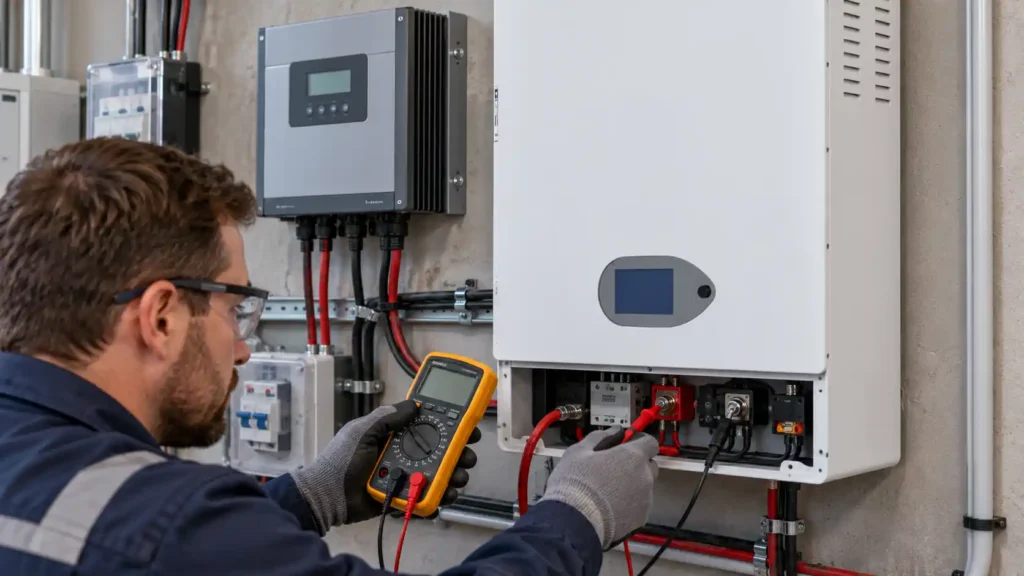
An MPPT solar charge controller regulates the voltage it can see. That voltage includes the drop across the cable, the fuse, the breaker and every connection between the controller and the battery. Under charge current, the terminal voltage at the controller is higher than the actual battery voltage by I × R.
Take a 48V pack charged at 100A through a 3m run of 35mm² cable. Copper at roughly 0.5 mΩ per metre gives about 3 mΩ for the round trip. At 100A that is 0.30V of drop. At 50A it is 0.15V.
Those numbers matter because LFP charge control operates on a 0.1V scale. The Victron manual’s own restart threshold for LiFePO4 is a fall to float voltage minus 0.1V sustained for one minute. A 0.15V sense error is larger than the hysteresis band the charger uses to decide whether to start a new charge cycle. The controller can therefore sit in float, convinced the bank is at setpoint, while the battery is a tenth of a volt low and drifting.
The same manual lists “battery cable voltage drop” as a documented cause of undercharged batteries, alongside an incorrect temperature compensation setting. Those two entries are the field failure, written down by the manufacturer.
The fix is either a thicker and shorter cable run, or a controller with a dedicated voltage sense input wired to the battery terminals rather than to the busbar. A sense wire carries almost no current, so it reads the battery rather than the cable. If the controller has no sense terminal, the next best option is to land the controller’s battery positive directly on the battery post and keep every other load on the busbar.
Temperature compensation should be off, and often is not
Lead-acid needs temperature compensation because its acceptable charge voltage moves with temperature, typically around −5 mV per °C per cell. On a 16S LiFePO4 pack, where series and parallel configuration is what fixes the per-cell figure, that same slope would move the setpoint by 1.6V across a 20°C swing, which is far too much for a chemistry whose upper voltage limit is fixed.
Victron disables compensation by default for LiFePO4, and VoltCrave Power’s own 51.2V packs publish a fixed charge cut-off of 58.4V rather than a temperature-dependent window. 58.4V across 16 series cells is 3.65V per cell, which is the number to compare against any profile a controller proposes.
If a controller applies lead-acid compensation to an LFP bank, two things happen depending on season. In cold weather the setpoint is pushed up and the pack is overcharged at the top of every cycle. In hot weather it is pushed down and the pack never reaches balancing voltage. Both look like “the controller charges fine” on a display and both shorten life quietly.
The check is one screen: if temperature compensation is enabled and the battery type is not lead-acid, that is a defect in the configuration, not a tuning preference.
Absorption time and the restart threshold interact badly with loads
Absorption time is not a fixed chemical requirement. It is the window during which the charger holds voltage high enough for the BMS to balance cells. Cut it short and the pack drifts out of balance over months, which then shows up as a BMS that cuts off early on the highest cell while the pack is still at 85%.
Two details in the manual matter here. The absorption timer starts when the charger reaches absorption voltage and pauses whenever output voltage falls below it, which happens when a load or a cloud pulls the bus down. And the charge cycle resets after an hour without charging.
In a system with a daytime load, a fridge cycling or an inverter carrying 2kW, the bus voltage sags every time the compressor starts. Each sag pauses the timer. The charger spends the afternoon toggling between absorption and float, never accumulating the full window, and the pack never gets the balancing time the profile assumed.
This is why fixed absorption time on LiFePO4 is usually better than an adaptive lead-acid algorithm. The adaptive version estimates state of charge from start-up voltage, which is exactly the measurement LiFePO4 makes hardest.
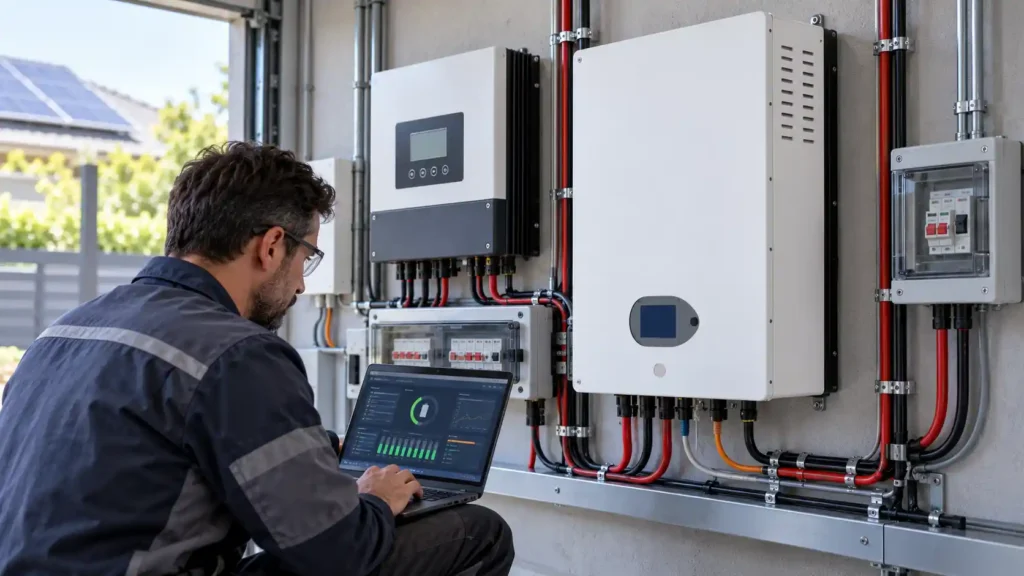
Where the BMS takes over, and where it disagrees
The BMS is the last line, and on a well-built pack it is not a subtle one. The protection set is documented in any competent LiFePO4 BMS, and VoltCrave Power’s 10.24kWh wall unit, for example, publishes a 58.4V charge cut-off, a 40V discharge cut-off, 100A maximum charge and discharge, and protection against over-charge, over-discharge, over-current, short circuit, high temperature and low-temperature charging.
That low-temperature cut-off is not a preference. LiFePO4 must not be charged below 0°C, because lithium plating at the anode is permanent. A controller with a 5°C cut-off and a BMS with a 0°C lock will disagree in the 0 to 5°C band, and the controller will keep trying while the BMS keeps refusing. Nothing fails, but nothing charges either, and the log looks like a controller fault.
The communication layer changes the picture again. A CAN-bus battery can send a charge voltage limit and a charge current limit to the system, and the controller then follows the battery instead of its own profile. Victron’s manual describes this explicitly, and also describes the ESS case where the solar charger’s algorithm is disabled entirely and the inverter/charger sets the curve. Once a BMS is in charge of the setpoints, the controller’s internal profile stops being the thing to tune.
That is the direction the industry is moving, and it is the reason a pack with a documented protocol is worth more than a pack with a good cell spec.
The five settings, in the order to check them
- Battery type. If the controller is on a lead-acid, AGM or gel profile, stop here. Nothing downstream can compensate.
- Absorption voltage. Convert to per-cell and compare with the pack datasheet. 56.8V on 16S is 3.55V per cell. 58.4V is 3.65V. A profile at 54.4V is 3.4V per cell, which will not fully charge and will not balance.
- Tail current. On LiFePO4 this should be 0A, or low enough that the full absorption window runs. A 2A default is a lead-acid value.
- Temperature compensation. Off. If the controller cannot disable it, it is the wrong controller for this bank.
- Sense point. Measure at the controller terminals and at the battery posts under load. A difference above 0.1V at absorption current is a wiring problem, not a settings problem.
One verification step closes the loop. After a full sun day, compare the controller’s reported state of charge with the shunt’s, and check the highest and lowest cell voltages in the BMS. A pack that reaches 100% on all three, with cell delta under 30mV, is actually full. A pack at 100% on the controller and 85% on the shunt is not.
What goes into the specification
For an OEM battery supply project or a residential home battery storage RFQ, a charge profile written as “LiFePO4” is not a specification. Six lines make it one:
- Absorption voltage and float voltage, stated per cell and as pack voltage at the configured series count
- Absorption time, and whether tail current termination is permitted
- Maximum charge current, and whether it is limited by the controller, the BMS or the pack
- Temperature compensation requirement, stated as disabled
- Low-temperature charging cut-off, and which device enforces it
- Whether the BMS publishes a charge voltage limit over CAN or RS485, and which protocol
The last line is the one that decides whether the system is tunable in five years. A pack that can tell the charger what to do survives a controller swap. A pack that cannot depends on whoever configured it the first time.
FAQs
Why does my MPPT solar charge controller show 100% when my battery is at 70%?
The controller is reporting the end of its absorption phase, not the battery’s state of charge. If the tail current is set to a lead-acid value or the cable drop is large, absorption ends while the pack is still short. Compare against a shunt before changing anything.
What absorption voltage should I use for a 48V LiFePO4 bank?
Convert the pack datasheet to per-cell. Common 16S pack cut-offs sit between 56.8V and 58.4V, which is 3.55V to 3.65V per cell. VoltCrave Power’s 51.2V packs publish 58.4V. Use the pack datasheet over any generic table.
Should temperature compensation be on for lithium?
No. LiFePO4 does not use the −5 mV/°C per cell slope that lead-acid needs. Leave compensation disabled and let the BMS handle low-temperature protection.
Can a charge controller overcharge a LiFePO4 battery?
Only if the profile is wrong or the BMS fails. The BMS cuts charging at the cell limit, so a correct profile plus a working BMS is two independent limits. A controller set to 58.4V on a pack whose BMS cuts at 58.4V will simply hand over to the BMS at the top of every cycle.
Is it a problem if my bank never reaches 100%?
For cycle life, not much. LiFePO4 does not need a full charge to avoid premature failure. For balancing and for state-of-charge accuracy, it is a problem, because the pack drifts and the reported percentage stops meaning anything. Treat a persistent 80% ceiling as a configuration defect, not a harmless habit.
Summary
Work the problem from the measurement backwards. If the controller and the shunt disagree, the MPPT solar charge controller is measuring its own terminals and ending absorption on a timer or a current threshold, so check cable drop and tail current first. If the BMS and the shunt disagree, the pack is out of balance and the fix is absorption time, not voltage.
The rule that covers most field cases: on a LiFePO4 bank, absorption voltage comes from the pack datasheet divided by the series count, absorption time is fixed rather than adaptive, tail current is zero, temperature compensation is off, and the sense point is the battery post. Any controller that cannot be configured to those five points is the wrong controller for the bank, no matter what its amp rating says.
Need help matching this topic to a real battery project?
Send your target application, capacity range, certification market, and order plan. VoltCrave can recommend a practical product direction.