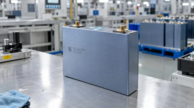
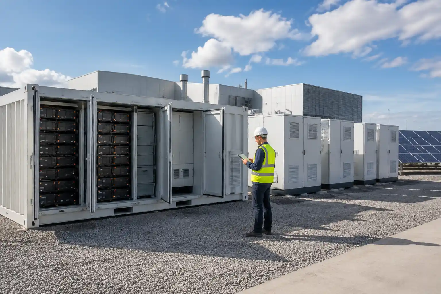
When buyers compare battery energy storage systems, the battery cabinet is often the most visible component. However, the system’s safety, power response, usable capacity, and long-term operating value also depend on three control layers:
- BMS: Battery Management System
- PCS: Power Conversion System
- EMS: Energy Management System
These systems are connected, but they do different jobs.
- The BMS protects and monitors the battery at the cell, module, rack, or container level.
- The PCS controls the flow of electrical power between the battery’s DC side and the site’s AC system.
- The EMS decides when, why, and how the complete energy storage system should operate.
A commercial BESS can contain high-quality battery cells and still perform poorly if the BMS, PCS, and EMS are not properly integrated. This guide explains the architecture in practical terms and provides a supplier evaluation checklist for project developers, installers, distributors, and energy storage buyers.
Quick Comparison: BMS vs PCS vs EMS
| Component | Primary role | Main operating domain | Typical questions |
|---|---|---|---|
| BMS | Monitor, protect, and manage the battery | Cell, module, rack, and battery DC system | Is the battery within safe voltage and temperature limits? |
| PCS | Convert and control electrical power | DC battery side and AC grid/load side | How much AC power can the system charge or discharge? |
| EMS | Optimize and coordinate system operation | Site, tariff, PV, grid, and customer application | When should the battery charge, discharge, or reserve energy? |
The U.S. Department of Energy describes the BMS as a hardware and software component that connects with the EMS and PCS to manage battery charging and discharging while monitoring cell conditions. Sandia National Laboratories describes the EMS as the layer used to monitor and optimally control energy storage as a flexible grid asset.
A Simple BESS Control Architecture
                    Utility Grid
                        |
                  AC switchgear
                        |
              +---------+---------+
              |       PCS       |
              |  DC <-> AC power |
              +---------+---------+
                        |
                    DC bus
                        |
             Battery racks and modules
                        |
                       BMS
        cell voltage, temperature, current,
        SOC, SOH, alarms, contactors, limits

  Site load, PV, tariff, forecast, and operating rules
                         |
                        EMS
         dispatch, scheduling, monitoring, reporting
The exact architecture varies by project. Some systems use rack-level BMS units, a master BMS, a site controller, and a cloud monitoring platform. Others combine several functions in an integrated controller. The names may differ between suppliers, so buyers should evaluate the actual functions and data flow rather than relying only on product labels.

What Does the BMS Do?
The BMS is the battery’s protection and monitoring layer. Its job is to keep the cells and battery assemblies within defined operating limits while reporting the battery’s condition to higher-level controls.
1. Cell voltage monitoring
The BMS monitors individual cell voltages and identifies abnormal differences between cells. Cell-level visibility is important because the weakest or most abnormal cell can restrict the usable performance of the entire series string.
Buyers should ask:
- What is the monitoring resolution?
- How frequently are cell values sampled?
- What voltage thresholds create warnings or shutdowns?
- How are abnormal cells isolated?
- Is historical cell data available?
2. Temperature monitoring
Temperature sensors help the BMS identify overheating, low-temperature charging conditions, and thermal imbalance between modules or racks.
The supplier should document:
- Sensor quantity and location
- Temperature measurement range
- Charging and discharging limits by temperature
- Alarm and shutdown thresholds
- Interaction with the thermal management system
3. Current and voltage protection
The BMS uses current and voltage data to protect against conditions such as overcharge, over-discharge, overcurrent, and short-circuit events. The protection chain may include contactors, fuses, breakers, relays, and emergency-stop functions.
The BMS should not be treated as a substitute for complete system protection. The battery cabinet, PCS, switchgear, fire protection, and site controls must work together.
4. SOC and SOH estimation
The BMS estimates:
- SOC, or state of charge: how much energy is available within the operating model
- SOH, or state of health: how the battery’s present condition compares with its original condition
These values are not always measured directly. They are calculated from current, voltage, temperature, operating history, and battery models. Buyers should ask how the supplier validates SOC and SOH accuracy under different temperatures, C-rates, and aging conditions.
5. Cell balancing
Cell balancing helps reduce voltage differences between cells. A BMS may use passive or active balancing, depending on the architecture and supplier design.
Important questions include:
- What balancing method is used?
- When does balancing occur?
- Is balancing available during charge, discharge, or standby?
- What is the balancing current?
- How does the system respond when cell imbalance exceeds the allowed limit?
6. Communication and fault reporting
The BMS communicates battery limits, alarms, SOC, SOH, and operating status to the PCS and EMS. Poor communication design can cause nuisance shutdowns, unavailable capacity, or unsafe control decisions.
Request a complete data-point list rather than a general statement that the system is “compatible.”
What Does the PCS Do?
The PCS is the power conversion and power-control layer between the battery’s DC system and the AC grid or facility.
1. Bidirectional AC/DC conversion
During charging, the PCS converts AC power into the DC power required by the battery. During discharging, it converts battery DC power into AC power for the facility or grid.
The PCS rating is normally expressed in kW or MW. It must be evaluated together with:
- Battery voltage range
- Continuous and peak power
- Charge and discharge limits
- AC connection voltage
- Grid frequency
- Efficiency curve
- Power factor and reactive power
- Overload capability
- Temperature derating
2. Power response and dispatch execution
The EMS may request a 200 kW discharge, but the PCS is the component that executes the AC power command. It controls the actual ramp rate, direction, and output within the limits provided by the BMS and the grid connection.
This is why a battery’s kWh rating does not describe the complete system power capability. The PCS, DC bus, contactors, cables, transformer, and protection equipment all affect the usable output.
3. Grid and site interface
The PCS may need to support functions such as:
- Grid synchronization
- Active power control
- Reactive power control
- Ramp-rate control
- Power factor control
- Islanding or backup operation, when designed for that application
- Interaction with PV inverters or generators
The required functions depend on the project interconnection and local requirements. Buyers should specify the intended application before comparing PCS models.
4. Power quality and thermal performance
Efficiency at full load is not enough to evaluate a PCS. A commercial system may spend significant time at partial load or standby. Request:
- Efficiency at multiple load points
- Standby consumption
- Noise level
- Operating temperature range
- Derating curve
- Harmonic performance
- Maintenance requirements
What Does the EMS Do?
The EMS is the system-level decision and coordination layer. It uses site information, operating rules, meter data, and battery status to determine the desired operating schedule.
1. Application dispatch
The EMS may control the BESS for:
- Peak shaving
- Time-of-use energy shifting
- Solar self-consumption
- Export limitation
- Backup reserve
- Demand response
- Renewable smoothing
- Microgrid operation
One BESS may support several functions, but the EMS must coordinate them. For example, a peak-shaving command should not consume the SOC reserve needed for an outage.
2. Load and PV coordination
The EMS receives information from:
- Revenue meters
- Facility meters
- PV inverters
- Generators
- Building management systems
- Utility or site controllers
- Weather or production forecasts, when used
It then creates charge, discharge, or standby commands for the PCS.
3. SOC reserve management
The EMS maintains operating limits such as:
- Minimum SOC
- Maximum SOC
- Backup reserve
- Charge and discharge windows
- Maximum daily throughput
- Temperature restrictions
- Battery availability
A good EMS should explain why a dispatch command was limited or rejected. If the system simply stops without an understandable reason, operators may not know whether the issue is the BMS, PCS, meter, tariff schedule, or communication layer.
4. Monitoring and reporting
The EMS should provide useful information about:
- Power and energy flow
- SOC and SOH
- Charge and discharge history
- Efficiency
- Alarms
- Availability
- Peak demand reduction
- PV energy shifted
- Revenue or savings metrics
- System downtime
Monitoring is not the same as optimization. A dashboard that displays data but cannot execute or verify the intended dispatch strategy may not deliver the expected project value.
How the Three Systems Work Together
Consider a commercial facility with a 500 kW / 1 MWh BESS. The project uses the system for peak shaving.
Step 1: The EMS identifies the event
The facility meter shows that site demand is approaching the configured grid import limit. The EMS calculates that a 300 kW discharge is required.
Step 2: The EMS sends a power request
The EMS sends a discharge command to the PCS. The command may include:
- Requested power
- Direction
- Ramp rate
- Duration
- SOC target
- Operating mode
Step 3: The PCS checks electrical limits
The PCS confirms that the AC connection, inverter temperature, DC voltage, and power limit support the requested output.
Step 4: The BMS checks battery limits
The BMS evaluates:
- Cell voltage
- Rack current
- Battery temperature
- SOC
- SOH
- Contactors
- Active alarms
If the battery can provide only 240 kW because of temperature or SOC limits, the BMS reports the available limit.
Step 5: The PCS follows the permitted command
The PCS discharges at the highest safe power allowed by the BMS and the electrical system.
Step 6: The EMS updates the dispatch
The EMS records the derating, maintains the required reserve, and adjusts the schedule. A properly integrated system should fail gracefully rather than continuing to request a power level that the battery cannot safely deliver.
Common Integration Problems Buyers Should Avoid
BMS and PCS communication mismatch
Two components may both support CAN or RS485, but that does not prove they are functionally compatible. The message structure, register map, timing, alarm logic, and control authority must also match.
EMS does not understand battery limits
If the EMS treats a nameplate battery rating as always available, it may request power that the BMS or PCS must reject. The EMS should receive dynamic limits, not only static specifications.
No clear control hierarchy
The project should define which system has authority during:
- Normal dispatch
- Overtemperature
- Communication loss
- Fire alarm
- Emergency stop
- Grid outage
- Manual maintenance
Safety commands should override economic dispatch commands.
Poor fallback behavior
Ask what happens when the EMS loses its connection to the cloud, meter, or site controller. The system may need a local control mode, safe standby mode, or predefined schedule.
Incomplete event logs
When a system fails to reduce demand or deliver backup power, the owner needs to identify the reason. Event logs should show:
- Original command
- BMS limit
- PCS response
- SOC and temperature
- Alarm status
- Meter data
- Communication status
Unclear warranty boundaries
The BMS, PCS, EMS, and battery may be supplied by different companies. The contract should state who is responsible when the complete system does not meet the guaranteed result.
Supplier Evaluation Checklist
BMS checklist
Ask the supplier to provide:
- Cell, module, rack, and master BMS architecture
- SOC and SOH estimation method
- Cell voltage and temperature sampling information
- Balancing method and balancing current
- Overvoltage, undervoltage, overcurrent, and temperature limits
- Contactor and pre-charge logic
- Alarm hierarchy
- Communication protocol and data-point list
- Local and remote emergency-stop behavior
- BMS test and validation records
PCS checklist
Verify:
- AC and DC rated power
- Continuous versus peak power
- Battery voltage range
- Charge and discharge efficiency
- Partial-load efficiency
- Power factor and reactive power capability
- Response time and ramp-rate control
- Operating temperature and derating
- Grid connection requirements
- Protection functions
- Maintenance and replacement plan
EMS checklist
Confirm:
- Supported operating modes
- Metering and control interfaces
- PV and generator integration
- Peak-shaving logic
- Time-of-use scheduling
- Backup reserve settings
- Manual override
- Local fallback mode
- Remote monitoring
- API or data export capability
- Alarm and event history
- Software update policy
- User permissions and cybersecurity documentation
System-level documentation
Request:
- Single-line diagram
- Control architecture diagram
- Communication map
- Complete data-point list
- Battery and PCS datasheets
- Operating limits by temperature and SOC
- Factory acceptance test procedure
- Site acceptance test procedure
- Commissioning plan
- Warranty responsibility matrix
- Spare-parts list
- Preventive-maintenance schedule
The U.S. Department of Energy’s Rapid Operational Validation Initiative guidance also emphasizes collecting data sheets for the cell, module or rack, BMS, converter or inverter, thermal management system, and complete BESS. This is a useful baseline for a commercial procurement package.
Internal Compatibility Questions for a BESS Project
Before approving a supplier, ask:
- Does the BMS expose dynamic charge and discharge limits?
- Can the PCS respond to those limits in real time?
- Can the EMS maintain a project-specific SOC reserve?
- Are meter readings fast and accurate enough for the tariff?
- Does the EMS record the reason for a derating or failed dispatch?
- Can the system operate safely when communications are interrupted?
- Are the BMS, PCS, and EMS software versions controlled?
- Does one company own final system integration responsibility?
- Can the supplier demonstrate the same architecture on a comparable project?
For broader procurement criteria, see the Energy Storage System Suppliers Guide and the Global Energy Storage Battery Certification Guide.
FAQs
Is the BMS the same as the EMS?
No. The BMS manages battery safety and condition at the cell, module, rack, or battery level. The EMS manages the complete energy storage system and its interaction with the site, tariff, PV system, grid, or generator.
Is the PCS the same as an inverter?
A PCS usually includes bidirectional power conversion and associated controls for an energy storage application. A standard PV inverter is not automatically suitable for battery charging and discharging.
Can the BMS control the entire BESS?
The BMS can enforce battery protection limits, but it is not normally responsible for economic dispatch, tariff optimization, or site-level scheduling. Those functions are typically handled by the EMS.
Which communication protocols are used?
Projects may use protocols such as CAN, RS485, Modbus, Ethernet-based interfaces, or utility and site-control protocols. Compatibility depends on the complete data map and control logic, not only the protocol name.
Can one supplier provide the BMS, PCS, and EMS?
Yes. Some suppliers offer an integrated solution, while others combine components from different vendors. An integrated solution may simplify responsibility, but buyers should still request independent component datasheets, test records, and clear warranty boundaries.
What is the most important supplier question?
Ask the supplier to demonstrate how the BMS, PCS, and EMS respond to a real operating event, including a power command, SOC limit, temperature derating, communication loss, and emergency stop.
Final Takeaway
BMS, PCS, and EMS are not interchangeable terms. They represent three different control layers:
- The BMS protects the battery.
- The PCS controls electrical power.
- The EMS coordinates the complete system.
The best BESS supplier is not simply the company with the largest battery cabinet or the longest feature list. It is the supplier that can demonstrate reliable communication, clear control authority, measurable performance, transparent documentation, and one accountable integration process.
VoltCrave Power supports LiFePO4 battery cells, custom battery packs, residential energy storage systems, portable power stations, and customized BESS solutions for global OEM, ODM, installer, and project customers. Explore the Battery Energy Storage System Manufacturer page or contact VoltCrave Power to discuss a project-specific system architecture.
References
- Battery Energy Storage Systems Report – U.S. Department of Energy
- Energy Storage Management Systems – Sandia National Laboratories
- Energy Storage System Pricing – Sandia National Laboratories
- Energy Storage Power Electronics Program – Sandia National Laboratories
- Lithium-Ion ROVI Requirements Overview – U.S. Department of Energy
Need help matching this topic to a real battery project?
Send your target application, capacity range, certification market, and order plan. VoltCrave can recommend a practical product direction.