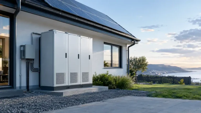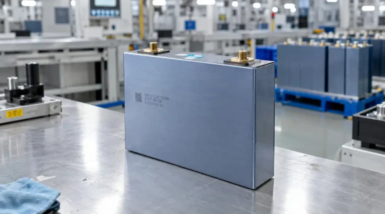
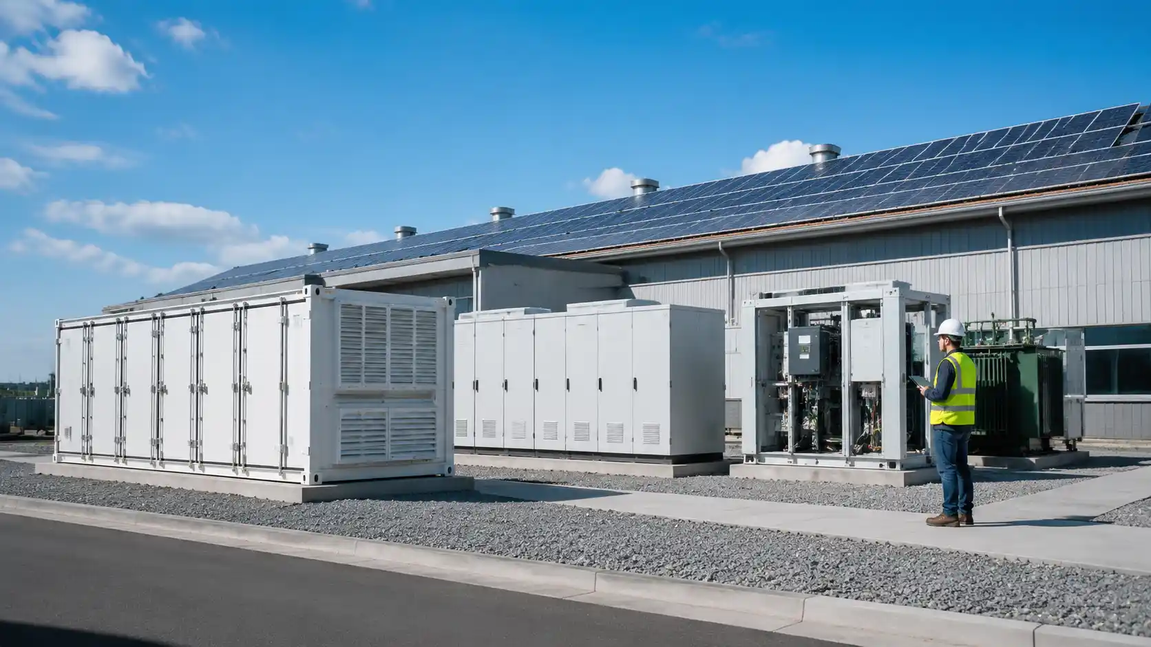
Sizing a commercial battery energy storage system is not simply a matter of choosing the largest battery available. A reliable design must match the system’s power rating, usable energy, operating schedule, battery chemistry, inverter capability, site load, tariff structure, and future operating requirements.
The most important distinction is simple:
- kW determines how much power the battery can deliver at one time.
- kWh determines how long the battery can deliver that power.
A commercial battery energy storage system that has enough kWh but not enough kW may fail to reduce a demand peak. A system with plenty of kW but insufficient kWh may start strongly and then stop before the peak event ends.
This guide explains how commercial buyers, project developers, and solar installers can size a BESS more accurately and prepare a better supplier request for quotation.
Quick Answer: What Determines Commercial BESS Size?
A commercial BESS should be sized around five questions:
- What application will create the system’s main value?
- What is the highest load or power event the system must manage?
- How many hours must the system charge or discharge?
- How much energy is available after depth of discharge, efficiency losses, reserve, and degradation?
- Can the PCS, EMS, grid connection, and site protection equipment support the requested operating profile?
The basic sizing relationships are:
Required battery power (kW) = Maximum power that must be supplied or reduced

Required delivered energy (kWh) = Required power (kW) x operating duration (hours)

Battery duration (hours) = Usable energy (kWh) / continuous power (kW)

Approximate C-rate = Power rating (kW) / Battery energy rating (kWh)
These formulas are useful for an initial estimate. A final design should use interval load data, dispatch simulations, electrical studies, and the supplier’s guaranteed operating limits.
kW, kWh, and C-Rate: The Three Numbers Buyers Must Separate
| Term | What it describes | Why it matters |
|---|---|---|
| kW | Instantaneous power | Determines whether the BESS can meet a peak load or critical load |
| kWh | Stored energy | Determines how long the system can operate |
| Duration | kWh divided by kW | Describes the expected discharge period |
| C-rate | Power divided by energy | Indicates how aggressively the battery is charged or discharged |
| Usable capacity | Energy available within the approved SOC window | More meaningful than nameplate capacity |
For example, a 500 kWh battery connected to a 250 kW PCS has an approximate two-hour duration and a 0.5C power-to-energy ratio. It does not mean that the system will always deliver exactly 500 kWh to the AC load. The usable result depends on the SOC window, efficiency, temperature, auxiliary consumption, and operating limits.
The U.S. Department of Energy’s BESS evaluation method separates demonstrated capacity, efficiency, and capacity ratio because nameplate capacity alone does not describe real-world performance. Buyers should apply the same discipline when comparing supplier proposals.
Step 1: Define the Primary BESS Application
The correct size depends on what the system is expected to do. A BESS designed for peak shaving may have a different power-to-energy ratio from a BESS designed for backup or solar shifting.
Peak shaving
The battery discharges when facility demand approaches a target threshold. The primary sizing question is:
How many kW must the battery provide, and for how long must the peak last?
Peak shaving is often power-sensitive. A short, high-power event may require a large PCS but only moderate battery energy. A long peak event may require both a high-power PCS and a larger battery block.
Solar self-consumption
The battery stores excess PV generation and discharges later when the facility load is higher than solar production. The design must compare:
- Hourly or sub-hourly PV output
- Facility load profile
- Solar export limits
- Desired evening discharge period
- Battery charging power
- Seasonal changes in solar production
Oversizing the battery does not automatically increase solar self-consumption. If there is not enough excess solar energy to charge it, the additional capacity may remain underused.
Time-of-use energy shifting
For time-of-use applications, the battery charges during lower-cost periods and discharges during higher-cost periods. The system must have enough usable energy to cover the target period and enough charge time to refill before the next event.
The tariff schedule is as important as the battery specification. If the high-price window changes by season, the EMS must be able to operate different schedules without creating an excessive SOC reserve.
Backup and resilience
Backup sizing starts with the critical loads, not the building’s total connected load. The design team should identify:
- Which circuits must remain online
- Whether motor starting loads are included
- Required backup duration
- Whether solar will operate during an outage
- Whether the system must island automatically
- Whether a generator will operate in parallel
A grid-connected PV system does not automatically provide power during a grid outage. The system needs appropriate islanding, transfer, protection, and control equipment.
Multiple use cases
Many commercial projects combine peak shaving, solar self-consumption, and backup. In that case, select a primary value stream first and then test the other use cases against the same operating limits. A battery cannot use the same energy twice unless the dispatch strategy and SOC reserve are carefully coordinated.

Step 2: Collect the Site Data Before Choosing a Battery
The quality of the sizing result depends on the quality of the site data. At minimum, request:
- Facility electricity demand data
- PV generation data, if applicable
- Utility tariff and demand-charge rules
- Critical load list
- Main service rating
- Transformer and switchgear limits
- Existing inverter specifications
- Available installation space
- Ambient temperature range
- Desired operating years
- Expected annual cycles
- Future load growth assumptions
Use the finest time interval that matches the utility’s demand measurement and the application’s control requirements. A monthly electricity bill is usually not enough to size a peak-shaving system because it does not show when the peaks occur, how long they last, or whether they are repeatable.
Build a load profile
A useful load profile should show:
- Daily maximum demand
- Average demand
- Duration of high-load events
- Weekend and weekday differences
- Seasonal changes
- Short spikes from motors or equipment
- Coincidence between PV production and facility demand
The objective is not to make the battery serve every load. The objective is to identify the specific load pattern that creates the business case.
Step 3: Calculate the Required Power in kW
For a basic peak-shaving design, use the following relationship:
Required battery discharge power
= Facility load during the event - Desired grid import limit
Example: Peak shaving
Assume a facility reaches a peak demand of 650 kW. The project team wants to limit grid import to 500 kW.
650 kW - 500 kW = 150 kW
The initial battery power requirement is therefore at least 150 kW at the point of interconnection. The final specification may need to be higher after considering:
- PCS conversion losses
- Metering location
- Control response time
- Power factor and reactive power
- Temperature derating
- Motor starting or transient loads
- Required control margin
The proposal should clearly state whether the supplier’s power rating is measured on the DC battery side or the AC output side. These are not interchangeable.
Do not confuse average load with peak load
An average facility load of 300 kW does not mean the BESS needs a 300 kW PCS. The correct value depends on the target event:
- Peak shaving uses the difference between actual demand and the target demand.
- Backup uses the simultaneous critical load.
- Solar shifting uses the charge and discharge profile created by PV and site demand.
- Frequency or power-quality applications may require fast response at a different duration.
Step 4: Calculate the Required Energy in kWh
Once the power requirement is known, estimate the energy required during the operating event:
Delivered energy (kWh) = Required discharge power (kW) x discharge duration (hours)
Using the previous example, suppose the facility must reduce 150 kW for 2.5 hours.
150 kW x 2.5 hours = 375 kWh delivered energy
This is the energy that must reach the intended load or grid connection point. It is not necessarily the battery’s nameplate capacity.
Convert delivered energy to rated battery capacity
A simple preliminary estimate is:
Rated battery capacity
= Required delivered energy / (usable SOC fraction x discharge efficiency)
If the design uses an 80% usable SOC window and assumes 95% discharge efficiency:
375 kWh / (0.80 x 0.95) = approximately 493 kWh
The preliminary system may therefore be specified as approximately 500 kWh, subject to the supplier’s guaranteed usable capacity, temperature curve, auxiliary consumption, and degradation warranty.
For a bankable project, do not treat this as a final answer. Ask the supplier to provide:
- Rated capacity
- Usable capacity at beginning of life
- Usable capacity at end of warranty
- Capacity at the requested discharge power
- SOC operating window
- Round-trip efficiency and its measurement point
- Auxiliary energy consumption
- Capacity retention or augmentation assumptions
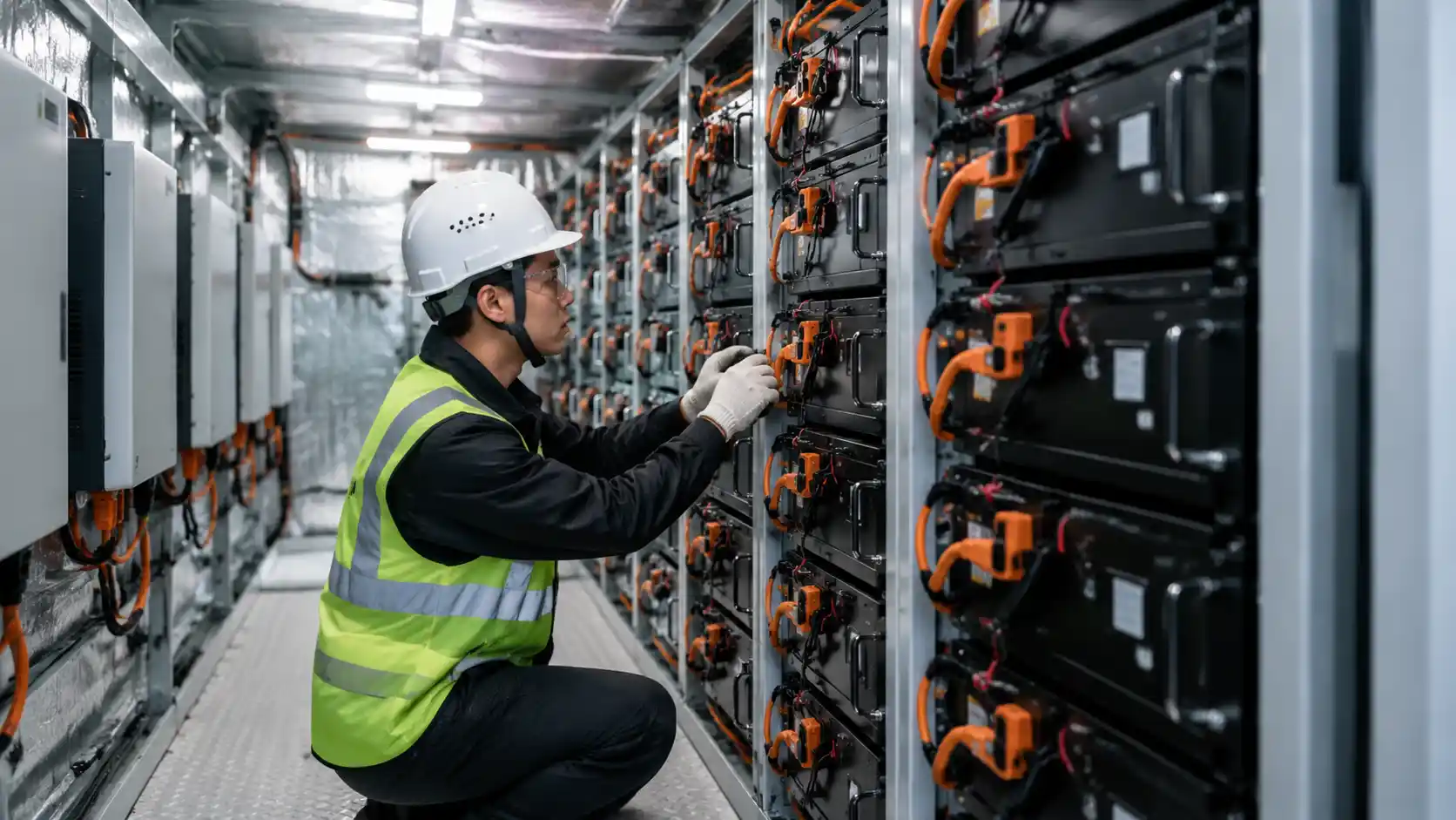
Step 5: Check Duration and C-Rate
Duration is calculated as:
Duration = Usable energy / continuous power
Consider three systems:
| System | Power | Energy | Approximate duration |
|---|---|---|---|
| A | 500 kW | 500 kWh | 1 hour |
| B | 250 kW | 500 kWh | 2 hours |
| C | 125 kW | 500 kWh | 4 hours |
All three systems have the same nameplate energy, but they are not equivalent. System A may suit a short, high-power event. System C may suit longer solar shifting or backup operation.
C-rate provides another useful comparison:
C-rate = Power / Energy
A 250 kW / 500 kWh system has an approximate 0.5C ratio. A 500 kW / 500 kWh system has an approximate 1C ratio. The supplier should confirm the allowed continuous and peak C-rate under the requested temperature, SOC, and warranty conditions.
Step 6: Include the Factors That Reduce Real Usable Capacity
Depth of discharge
A battery may be rated at 500 kWh but operated within a narrower SOC window to protect life and preserve emergency reserve. Always compare usable capacity, not only rated capacity.
Round-trip and discharge efficiency
Energy is lost during charging, discharging, conversion, cooling, and other auxiliary operations. Ask whether the stated efficiency is:
- DC-to-DC
- AC-to-AC
- Measured at rated power
- Measured at a specific SOC window
- Measured with or without auxiliary loads
Temperature
Battery and power electronics performance may change with temperature. The supplier should provide power and energy performance at the project’s expected ambient conditions, not only at a laboratory reference temperature.
Degradation
The battery may need to meet the project requirement after several years of operation, not only on day one. Include:
- Annual cycle count
- Expected depth of discharge
- Temperature profile
- Calendar aging
- Warranty capacity threshold
- Augmentation or replacement plan
Parasitic and balance-of-plant loads
HVAC, pumps, controls, fire protection, lighting, communications, and standby equipment consume energy. These loads should be identified in the system energy model.
Future expansion
If the facility expects load growth, confirm whether the system supports:
- Additional battery racks
- Additional PCS capacity
- EMS expansion
- Compatible replacement modules
- Protection and transformer upgrades
Three Practical Sizing Examples
Example 1: Commercial peak shaving
Project requirement:
- Maximum facility demand: 650 kW
- Desired grid import limit: 500 kW
- Peak duration: 2.5 hours
- Usable SOC window: 80%
- Estimated discharge efficiency: 95%
Initial result:
- Power: 150 kW minimum
- Delivered energy: 375 kWh
- Preliminary rated energy: approximately 493 kWh
- Practical starting point: approximately 150 kW / 500 kWh, subject to simulation
Example 2: Solar self-consumption
Assume a site has 300 kW of excess solar generation for four hours, but the actual excess changes throughout the day.
A simple upper-bound estimate is:
300 kW x 4 hours = 1,200 kWh
However, a time-series simulation may show that the average excess is only 210 kW. The actual energy requirement would then be closer to:
210 kW x 4 hours = 840 kWh
This is why a load and PV profile is more valuable than a single peak number.
Example 3: Critical-load backup
Assume the critical load is 80 kW and the required backup duration is six hours.
80 kW x 6 hours = 480 kWh delivered energy
480 kWh / (0.80 x 0.95) = approximately 632 kWh rated capacity
The design must still verify motor starting current, HVAC loads, transfer time, islanding capability, and whether PV can recharge the battery during the outage.
What to Put in a Commercial BESS RFQ
A weak RFQ asks for a battery size. A useful RFQ defines the operating result.
Include:
- Required AC power at the point of interconnection
- Required usable AC energy
- Minimum and maximum SOC
- Charge and discharge schedule
- Maximum response time
- Ambient temperature and installation altitude
- Annual cycles and warranty period
- Efficiency measurement method
- Grid connection voltage and frequency
- PV, generator, or UPS integration requirements
- EMS functions and communication requirements
- Safety, testing, commissioning, and documentation requirements
- Capacity retention and augmentation assumptions
- After-sales service and spare-parts expectations
For more supplier-selection guidance, see the Energy Storage System Suppliers Guide and the Battery Energy Storage System Manufacturer Guide.
Commercial BESS Sizing Checklist
Before approving a proposed system, confirm:
- The power rating is stated at the correct AC or DC measurement point.
- The usable energy is defined at the required discharge power.
- The system can meet the requirement at the expected temperature.
- Efficiency includes the measurement boundary you need.
- The SOC reserve is included in the model.
- Battery degradation is included in the long-term case.
- EMS dispatch logic has been tested with actual site data.
- PCS, transformer, switchgear, and protection limits are compatible.
- Critical loads and starting currents are documented.
- Expansion, warranty, and replacement assumptions are clear.
FAQs
Can I size a commercial BESS from the monthly electricity bill?
Usually not. A monthly bill may show total energy and billing demand, but it does not show the shape and duration of the events. Use interval load data whenever possible.
Is a larger battery always better?
No. A larger system may increase capital cost without increasing savings if the site does not have enough peak duration, excess solar, or tariff spread to use the additional energy.
Should I choose the battery or PCS first?
Neither should be selected in isolation. The target application determines the power-to-energy ratio, and the PCS must be matched to the battery voltage range, grid connection, control requirements, and site power limit.
What is more important: kW or kWh?
It depends on the application. Peak shaving may be power-limited, while backup and solar shifting may be energy-limited. Most commercial projects require both to be analyzed together.
How can I improve the accuracy of a supplier proposal?
Provide interval load data, tariff rules, PV production data, critical-load information, operating temperature, and the desired warranty outcome. Ask suppliers to return a dispatch simulation instead of only a product brochure.
Final Takeaway
Commercial battery energy storage system sizing should start with the site’s operating problem, not a standard battery model. Define the application, analyze the load profile, calculate the required kW and kWh, then adjust for SOC limits, efficiency, temperature, degradation, auxiliary loads, and future expansion.
The most useful supplier comparison is not:
Which battery has the largest nameplate capacity?
It is:
Which system can deliver the required power and usable energy at the point of interconnection, under real operating conditions, for the required project life?
VoltCrave Power supports residential, portable, and commercial energy storage projects with LiFePO4 battery cells, battery packs, all-in-one ESS products, and customized energy storage solutions. For a project-specific sizing discussion, visit the Energy Storage Solutions page or contact VoltCrave Power.
References
- Battery Energy Storage System Evaluation Method – U.S. Department of Energy
- On-Site Energy Storage Decision Guide – U.S. Department of Energy
Need help matching this topic to a real battery project?
Send your target application, capacity range, certification market, and order plan. VoltCrave can recommend a practical product direction.