If you already have a hybrid solar inverter, the first question is usually: how many solar panels can you connect to it?
A common shortcut is to divide the inverter’s rated power by the panel wattage. For a 6 kW inverter and 550 W panels, that gives roughly 11 panels.
That calculation is not enough. The actual panel count can be lower or higher depending on the inverter’s maximum PV voltage, MPPT voltage range, maximum PV input current, PV input power, and battery charging limit.
For PV matching, check the limits in this order:
Voltage first, current second, and total PV power third.
The reason is simple. A panel array can stay below the inverter’s kW rating and still exceed its maximum PV voltage or input current. Conversely, an inverter may accept more DC panel capacity than its AC output rating because the array is expected to operate below STC conditions for much of the day.
This article uses specifications from VoltCrave Power’s hybrid inverter and solar panel range to show how to calculate string length, parallel strings, MPPT configuration, PV oversizing, and later expansion. You can verify the figures against the relevant hybrid inverter and solar panel range.
If you have not selected the inverter yet, determine the system architecture first. Our comparison of off-grid and hybrid inverters explains the main differences in how the two systems operate when the grid is unavailable.
What determines how many solar panels you can connect to a hybrid inverter?
Five specifications normally determine the usable PV configuration:
| Limit | Where to find it on the datasheet | What it affects |
|---|---|---|
| Maximum PV input voltage | Maximum PV Input Voltage | Maximum number of panels in one series string |
| MPPT voltage range | MPPT Tracking Range | Whether the string can operate and track correctly |
| Maximum PV input current | Maximum PV Input Current | Maximum number of parallel strings per MPPT |
| Maximum PV input power | PV Input Power | Total DC array size and potential clipping |
| Battery charge acceptance | Maximum Charging Current × battery voltage | How much surplus PV the battery can absorb |
The first four are direct inverter-side limits. Battery charge acceptance becomes relevant when the PV array can produce more power than the battery and loads can absorb.
This is why matching panels to a hybrid inverter is more than comparing the inverter’s kW rating with the panel wattage.
1. Check the inverter’s PV specifications first
Take a real example. The following specifications are from VoltCrave Power’s 6 kW AL-All 486000Pro hybrid inverter (product page):
| Parameter | Specification |
|---|---|
| Rated output power | 6000 W |
| PV input power | 6000 W |
| MPPT input voltage range | 120–500 Vdc |
| MPPT optimal working voltage range | 300–400 Vdc |
| Maximum PV input voltage | 500 Vdc |
| Maximum PV input current | 20 A |
| Maximum charging current | 120 A |
| Battery rated voltage | 48 Vdc |
| Peak power | 12000 VA |
| Switching time | 10 ms (typical) |
| Communication | BMS / RS232 / RS485 / CAN / USB |
| Working temperature | −10 to 50 °C |
Three voltage specifications are particularly easy to confuse.
MPPT input voltage range: 120–500 Vdc
This is the voltage range in which the MPPT can track the PV array.
If the operating voltage falls below the lower limit, the inverter may not be able to start or continue tracking. If the array operates outside the specified range, normal MPPT operation cannot be assumed.
MPPT optimal working voltage range: 300–400 Vdc
This is the preferred operating range published for this inverter.
A string can be technically within the MPPT tracking range without operating inside the optimal range. That distinction becomes important when module voltage falls at high cell temperatures.
Maximum PV input voltage: 500 Vdc
This is the hard upper limit. It determines how many modules can safely be connected in series.
For string sizing, this is the number that must be checked against the cold-weather open-circuit voltage (Voc) of the array.
Write these values down before selecting the module configuration.
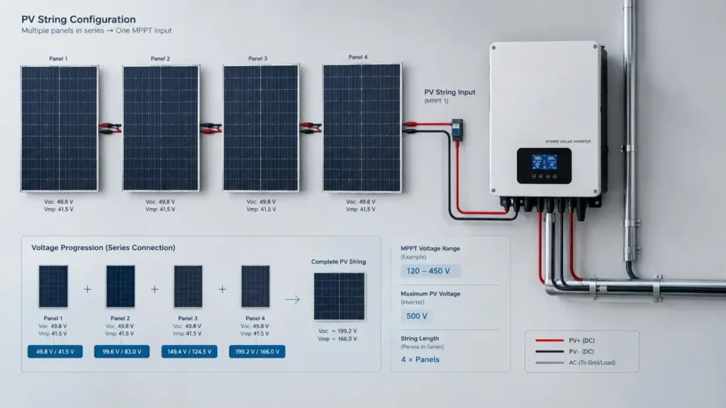
2. Calculate cold-weather Voc before deciding the string length
A solar module’s open-circuit voltage increases as temperature falls. This means the highest string voltage may occur on a cold morning when the array is not yet under load.
The calculation is:
Voc(cold) = Voc(STC) × [1 + βVoc × (T_min − 25)]
Where:
- Voc(STC) is the module’s open-circuit voltage at STC
- βVoc is the module’s Voc temperature coefficient
- T_min is the site’s minimum design temperature in °C
- 25°C is the STC reference temperature
For VoltCrave’s design examples, we use a 98% design ceiling of the inverter’s maximum PV voltage. For a 500 V maximum PV input, that gives:
500 V × 98% = 490 V
This 2% margin is a VoltCrave engineering design practice, not a universal industry requirement. The actual module temperature coefficient and the inverter manufacturer’s installation requirements should always take priority.
Example: 550 W solar panel on a 500 V hybrid inverter
The example module is a 550 W 144-cell monocrystalline solar panel (product page) with:
- Voc: 49.95 V
- Vmp: 41.97 V
For the following calculation, use a conservative βVoc of −0.35%/°C as the example coefficient.
| Site design minimum | Voc per panel | Maximum panels per string at 490 V | String Voc |
|---|---|---|---|
| +15 °C | 51.7 V | 9 | 465 V |
| +5 °C | 53.5 V | 9 | 481 V |
| 0 °C | 54.3 V | 9 | 489 V |
| −10 °C | 56.1 V | 8 | 449 V |
The important point is that the maximum number of panels in a string depends on both the inverter and the installation site’s minimum temperature.
The same 500 V inverter can take nine of these 550 W modules per string at a warm site, while a site reaching −10 °C requires the string to be limited to eight modules under this design rule.
Why 10 panels do not work in this example
At STC:
10 × 49.95 V = 499.5 V
That is already almost the full 500 V maximum at 25 °C. As temperature falls, Voc rises further.
At −10 °C, the calculated string voltage is about:
10 × 56.1 V = 561 V
That exceeds the inverter’s 500 V maximum PV input.
No inverter setting can make an over-voltage string safe. The string must be redesigned.
What happens if the PV voltage exceeds the inverter limit?
An array operating above the inverter’s specified maximum PV voltage can overstress the MPPT input stage, including switching components and DC bus components. The result can be permanent hardware damage rather than simple MPPT shutdown.
For that reason, the maximum PV voltage in the inverter datasheet should be treated as a hard limit.
Warranty coverage also depends on the manufacturer’s specified operating conditions. PV damage caused by an incorrectly designed array may fall outside those conditions.
This is why the module’s Voc temperature coefficient matters when designing a string. A datasheet that lists Voc but does not provide the temperature coefficient leaves an important part of the cold-weather calculation unresolved.
3. Check hot-weather Vmp to make sure the string stays inside the MPPT range
The cold-weather calculation protects the inverter from excessive voltage.
The hot-weather calculation answers a different question:
Will the string still produce a useful operating voltage when the modules are hot?
Module voltage decreases as cell temperature rises. Using the same example module and a βVmp of −0.35%/°C:
- Vmp at STC: 41.97 V
- Assumed cell temperature: 65 °C
- Calculated Vmp per module: approximately 36.1 V
The resulting string voltage is:
| Panels per string | Vmp at STC | Vmp at 65 °C | Compared with 300–400 V optimal range |
|---|---|---|---|
| 8 | 336 V | 289 V | Below optimal range |
| 9 | 378 V | 325 V | Inside optimal range |
| 10 | 420 V | 361 V | Inside optimal range, but fails the cold-voltage check |
This shows the basic design trade-off:
- Too few panels can leave the string below the inverter’s preferred MPPT operating range when the modules are hot.
- Too many panels can push the string above the inverter’s maximum PV voltage when the modules are cold.
For this example, nine panels per string satisfy both checks under the stated temperature assumptions.
The practical rule is:
Choose the longest string that passes the cold-voltage check while keeping hot-weather operating voltage above the MPPT minimum.
The exact result depends on the inverter and module datasheets and the installation site’s temperature range.
A string can also be too short
Consider the VoltCrave 300 W 60-cell module with a Vmp of 32.8 V.
If the inverter’s MPPT tracking floor is 120 V and the module’s Vmp falls to approximately 28.2 V at 65 °C:
- 4 modules: 4 × 28.2 V = 113 V → below the tracking floor
- 5 modules: 5 × 28.2 V = 141 V → above the tracking floor
A system that operates normally in the morning can therefore lose PV production during the hottest part of the afternoon if the string is too short.
4. Check PV current before adding parallel strings
Series wiring increases voltage.
Parallel wiring increases current.
Once the maximum string voltage has been established, the next question is how many strings can be connected to each MPPT.
For the 550 W module in this example:
Imp = 13.11 A
If two identical strings are connected in parallel:
13.11 A × 2 = 26.22 A
That is acceptable only when the inverter’s input current limit for that MPPT is at least 26.22 A.
Here is how the same 550 W module interacts with several VoltCrave hybrid inverter configurations:
| Inverter | Maximum PV input current | 550 W strings | Result |
|---|---|---|---|
| 6 kW AL-All 486000Pro | 20 A | 1 string | 2 × 13.11 A = 26.22 A, above limit |
| IP66 6.6 kW | 2 × 21 A | 1 per tracker | 2 × 13.11 A = 26.22 A, above each 21 A input |
| IP66 8.6 / 10.6 kW | 2 × 27 A | 2 per tracker | 26.22 A is within the 27 A limit |
| 18 kW KA18048SS | 3 × 27 A | 2 per tracker | 26.22 A is within the 27 A limit |
| 33 kW KA33048SS | 6 × 18 A | 1 per tracker | Additional MPPTs reduce the need for parallel strings |
The important detail is that the current limit must be checked per MPPT, not only against the inverter’s total rated power.
5. A 9 × 550 W array can behave differently from a 17 × 350 W array
The effect of PV current becomes clearer when two different module sizes are compared on the same 6 kW inverter.
Option A: 9 × 550 W
One string gives:
- Total PV power: 4,950 W
- Imp: 13.11 A
- Vmp at STC: 378 V
- DC/PV rating ratio: 0.83×
A second 550 W string would produce:
2 × 13.11 A = 26.22 A
That exceeds the inverter’s 20 A maximum PV input current.
Option B: 17 × 350 W
The 350 W module has an Imp of approximately 9.6 A.
Using two strings of 9 and 8 modules:
- Total PV power: 5,950 W
- Parallel current: 2 × 9.6 A = 19.2 A
- DC/PV rating ratio: 0.99×
- String voltages under the +5 °C design condition: approximately 442 V and 393 V
Both strings remain within the stated 490 V design ceiling.
The two configurations show why module wattage alone does not determine the usable array size. A lower-wattage module can allow a different string and parallel configuration because its voltage and current characteristics are different.
When comparing modules for a hybrid inverter, check Voc, Vmp, Imp, Isc, and the temperature coefficients, not only Pm.
What about string fusing?
String protection depends on the module’s maximum series fuse rating, the number of parallel strings, the combiner/inverter design, and applicable electrical codes.
Do not apply a fixed “two strings need no fuse, three strings need a fuse” rule to every installation.
If strings are paralleled, check the module manufacturer’s maximum series fuse rating, Isc, the inverter or combiner requirements, and local electrical requirements before finalizing the design.
6. How much PV can you oversize on a hybrid inverter?
The inverter’s AC output rating and its allowable DC PV input are not necessarily the same number.
In hot, dusty or hazy environments, modules often operate below their STC nameplate power because cell temperature, soiling, irradiance and other site conditions reduce actual output.
For that reason, some hybrid inverter platforms allow the PV array to exceed the inverter’s AC output rating.
VoltCrave’s own product range includes different DC/AC ratios. For example, the IP66 hybrid series accepts up to 12,000 W of PV on a 6,600 W inverter, equivalent to approximately 1.82× the AC rating.
The important point is that the manufacturer’s stated PV input limits still apply.
What happens when the array produces more power than the inverter can use?
If the PV array can produce more DC power than the inverter can process at that moment, the inverter can reduce PV operating power. This is commonly referred to as clipping.
Clipping itself is not the same as exceeding the inverter’s electrical limits. The array must still remain within the specified:
- Maximum PV input voltage
- Maximum PV input current
- Maximum PV input power
- MPPT operating range
A hybrid inverter may also use available PV power to charge the battery when the loads do not consume it.
The battery creates another power limit
Battery charging becomes relevant when the PV array can produce more power than the battery can accept.
For the 6 kW AL-All 486000Pro:
- Maximum charging current: 120 A
- Battery rated voltage: 48 V
A simple nominal calculation gives:
120 A × 48 V ≈ 5.8 kW
The 9 × 550 W array is rated at 4.95 kW, so its STC nameplate power is below this nominal charging-power figure.
A larger PV array can still be useful, but the inverter and battery may limit how much power is actually stored at a given moment. Available PV may first supply the loads, with the remaining power going to battery charging until the relevant charging limit is reached.
If you are sizing the battery at the same time, the battery’s required usable capacity and charging/discharging limits should be evaluated separately. See the 5 kWh hybrid home energy storage sizing article for that side of the design.
Hybrid inverter panel-count reference table
The following table applies the voltage, current and PV power checks to selected VoltCrave hybrid inverter models using the 550 W module described above.
The example assumes a +5 °C design minimum. The −10 °C column shows how the maximum string length changes in a colder environment.
| Inverter | Max PV voltage | Panels/string at +5 °C | Panels/string at −10 °C | Trackers / strings | Total panels | Array size | DC/AC ratio | Main limiting factor |
|---|---|---|---|---|---|---|---|---|
| 6 kW AL-All 486000Pro | 500 V | 9 | 8 | 1 / 1 | 9 | 4,950 W | 0.83× | 20 A PV input current |
| 8.6 / 11 kW dual MPPT | 500 V | 9 | 8 | 2 / 2 | 18 | 9,900 W | 1.15× / 0.90× | 5,500 W PV per tracker |
| IP66 8.6 kW | 500 V | 9 | 8 | 2 / 2 | 18 | 9,900 W | 1.15× | 8,600 W charging power |
| 18 kW three-phase | 500 V | 9 | 8 | 3 / 3 | 27 | 14,850 W | 0.83× | 27 A input allows up to 2 strings per tracker |
| 33 kW three-phase | 500 V | 9 | 8 | 6 / 6 | 54 | 29,700 W | 0.90× | 450 A charge acceptance |
Use this table as a reference rather than a finished installation design. The same module can produce very different array configurations depending on the inverter’s MPPT count, voltage range, current limit and PV input power.
How should strings be split across multiple MPPTs?
Use separate MPPTs for different orientations when possible.
For example, if one roof faces east and another faces west, independent MPPTs allow each array to operate at its own maximum power point.
If strings are paralleled, keep the strings matched.
Use the same module type and the same number of modules per string. Mixing strings with substantially different voltage or current characteristics can reduce array performance and complicate MPPT operation.
Do not mix fundamentally different module configurations in the same string.
For example, a 60-cell module and a 144-cell module should not be combined in the same series string simply because their nameplate wattages appear compatible.
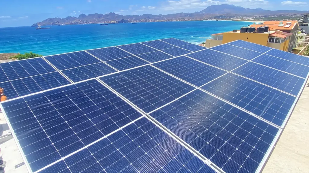
Worked design: tropical rooftop hybrid system, 13.2 kW PV / 15 kWh battery
One of the residential hybrid installations in VoltCrave’s project case library uses a 13.2 kW PV array and 15 kWh battery for household backup and self-consumption.
The PV array contains:
24 × 550 W = 13.2 kW
For an 8.6 kW dual-tracker inverter, the 550 W modules can be arranged as:
- Tracker 1: 9 panels in series = 4,950 W
- Tracker 2: 9 panels in series = 4,950 W
- Remaining 6 panels: require a separate compatible MPPT/string arrangement or should be reserved for a future expansion, depending on the inverter’s current and voltage limits
The 9-panel string reaches approximately 481 V at +5 °C under the stated temperature assumptions and approximately 325 V at 65 °C.
Both values fit the example inverter’s design requirements:
- Cold voltage remains below the 490 V design ceiling.
- Hot Vmp remains inside the 300–400 V optimal range.
On a three-MPPT 18 kW inverter, another possible arrangement is three strings of eight modules:
3 × 8 × 550 W = 13.2 kW
This gives equal string lengths and separate MPPT tracking.
The PV array can also produce more power than the battery can absorb at a given moment. With a nominal 150 A × 48 V charging figure of approximately 7.2 kW for the cited battery configuration, the remaining PV power can supply household loads or be curtailed when the system has no additional demand.
The exact energy flow depends on the inverter, battery, loads and operating mode.
Worked design: hot, dusty, weak-grid off-grid system, 10 kW / 10 kWh
A second design pattern applies to hot, dusty, weak-grid installations.
Using:
18 × 550 W = 9.9 kW
the array can be arranged as two strings of nine panels on a suitable dual-MPPT inverter.
At the +5 °C example temperature:
9 × 53.5 V ≈ 481 V
At 65 °C cell temperature:
9 × 36.1 V ≈ 325 V
The string therefore remains within the stated voltage limits under both the cold and hot checks.
In a hot and dusty environment, the reason for selecting close to 1.0× DC/AC capacity is not simply the nameplate calculation. Real operating conditions can reduce module output because of temperature and soiling.
For an off-grid system, keeping the PV string above the MPPT operating floor during the hottest part of the day is especially important because there may be no grid supply available to cover the load when PV production falls.
Worked design: high self-consumption rooftop, 24 kW PV
A third design pattern uses 44 × 550 W modules, giving:
44 × 550 W = 24.2 kW
On a 33 kW three-phase inverter with six MPPTs, one possible configuration is:
- Four strings of 9: 36 panels = 19,800 W
- One string of 8: 4,400 W
- One MPPT: left available for future expansion, subject to the inverter’s specifications
The four 9-panel strings each provide 4,950 W, which is below the cited 5,500 W per-tracker PV limit.
The total array is approximately 24.2 kW, or about 0.73× the inverter’s 33 kW AC rating.
The inverter’s 450 A charge-current specification corresponds to approximately 21.6 kW at a nominal 48 V battery voltage, so the battery’s charging capability becomes another constraint on how much of the PV array can be stored at any given time.
The key design point is that PV capacity, inverter capacity and battery capacity should be checked together rather than sized independently.
Already have a system? Check these limits before adding more panels
PV expansion is where an otherwise correct system can become non-compliant.
There are three common expansion routes:
| Expansion route | Test to run | Example result on a 500 V inverter |
|---|---|---|
| Add a panel to an existing string | Recalculate cold-weather Voc | 10 panels = 561 V at −10 °C → not acceptable |
| Add a parallel string to the same MPPT | Imp × number of strings ≤ MPPT current limit | 2 × 13.11 A = 26.22 A into a 20 A input → not acceptable |
| Add PV to a spare MPPT | Check that the additional MPPT has suitable voltage, current and power limits | Can be viable if all limits are satisfied |
Three practical rules follow.
1. Check available MPPT capacity, not just spare inverter wattage
An unused MPPT can provide a straightforward expansion path. A fully utilized single-MPPT input may have no practical way to accept another string even if the inverter’s total AC rating appears large enough.
2. Recalculate the cold-weather voltage after adding modules
Adding one module to a series string changes the maximum Voc. The calculation must be repeated using the site’s minimum design temperature.
3. Match the module to the electrical limits, not only the price per watt
The 9 × 550 W versus 17 × 350 W example shows why the lowest module price per watt does not automatically produce the most usable array.
Pre-purchase hybrid inverter and solar panel matching checklist
Before ordering the equipment, confirm these values from the actual inverter and module datasheets.
- Maximum PV input voltage: ______ V
VoltCrave design ceiling at 98%: ______ V - Site minimum design temperature: ______ °C
Use an appropriate site record rather than the annual average. - Module Voc temperature coefficient: ______ %/°C
- Cold-weather Voc per module:
Voc(STC) × [1 + βVoc × (T_min − 25)] = ______ V - Maximum panels per string: ______
Round the calculated result down. - Hot-weather string Vmp:
Vmp(STC) × [1 + βVmp × (65 − 25)] × panels per string = ______ V
Confirm that this remains above the MPPT tracking floor and preferably within the inverter’s optimal operating range. - Maximum PV input current: ______ A
Parallel strings × Imp = ______ A
Confirm the result does not exceed the applicable MPPT current limit. - PV input power: ______ W
Total modules × module Pm = ______ W - Battery charge acceptance:
Maximum charging current × nominal battery voltage = ______ W
Compare this with the PV array when evaluating how much solar energy can actually be stored. - Available MPPT trackers for future expansion: ______
This checklist is more useful than calculating the panel count from inverter kW alone.
FAQs
How many 550 W panels can I connect to a 6 kW hybrid inverter?
For the 6 kW AL-All 486000Pro example, nine 550 W panels can be connected in one string under the stated +5 °C design condition.
That gives:
9 × 550 W = 4,950 W
The configuration is limited by the inverter’s 500 V maximum PV input voltage and 20 A maximum PV input current, rather than simply by its 6,000 W rated output.
In a colder −10 °C environment, the same module example is limited to eight panels per string under the stated 490 V design ceiling.
Can I connect more solar panels than the inverter’s kW rating?
Sometimes, yes.
The inverter’s datasheet must allow the proposed DC array size, and the design must remain within the maximum PV voltage, current and power limits.
Some hybrid inverter platforms are specifically designed to accept a DC array larger than their AC output rating. The benefit is that the array can produce closer to its useful output under conditions where module temperature, irradiance and soiling reduce actual power.
The allowable DC/AC ratio is model-specific.
What happens if my PV string voltage is too high?
If the array exceeds the inverter’s specified maximum PV input voltage, the MPPT input stage can be overstressed and damaged.
The risk is highest under cold conditions because module Voc increases as temperature falls.
Always calculate string Voc at the site’s minimum design temperature before finalizing the panel count.
Can I mix 450 W and 550 W panels on one MPPT?
It depends on the electrical characteristics and configuration, but mixing different modules is generally undesirable when the strings are not closely matched.
In a series string, the current is constrained by the module with the lowest usable current.
In parallel, the strings should have closely matched operating voltages and current characteristics, with the same number of modules per string where applicable.
For a new installation, using matched modules across a string or parallel group is usually simpler to design and verify.
Do I need fuses when I parallel solar panel strings?
There is no single rule that applies to every configuration.
Check:
- module maximum series fuse rating
- module Isc
- number of parallel strings
- inverter or combiner requirements
- applicable electrical codes
For multiple parallel strings, the protection arrangement should be confirmed from the module and inverter documentation rather than applying a fixed string-count rule.
Why does my solar array stop producing in the afternoon heat?
Two common possibilities are:
- The string voltage has fallen below the MPPT tracking floor.
This can happen when the modules become hot and Vmp drops. - The battery is full and the loads cannot absorb the available PV power.
In that situation, the hybrid inverter may reduce PV production because there is no additional load or battery capacity available.
The first is a PV string configuration issue. The second is an energy-management or battery-capacity issue.
Get your PV string design checked before you buy
VoltCrave Power has been manufacturing LiFePO4 energy storage and hybrid inverter systems since 2011, with production bases in Dongguan, Hunan and Thailand, an in-house ISO/IEC 17025 test laboratory, and products certified to UL 1973, IEC 62619, UN38.3, CE and RoHS. More information is available on the VoltCrave Power Supply Certification Page.
For a string-design check, provide:
- Your inverter model and its datasheet
- Your selected solar module datasheet, including Voc, Vmp, Imp, Isc and temperature coefficients
- The installation site and minimum design temperature
The resulting design should give you three things:
- the maximum number of panels per string
- the recommended string and MPPT configuration
- the maximum parallel current that the inverter input can accept
The two numbers that should never be exceeded are the maximum PV string voltage under the site’s coldest design condition and the maximum PV input current for the applicable MPPT.
Need help matching this topic to a real battery project?
Send your target application, capacity range, certification market, and order plan. VoltCrave can recommend a practical product direction.